S E C T I O N General Operation Section 3 3.1 Turning Power On and Setting Volume 3.1.1 Power Up Power is turned on and off by the top panel ON-OFF/Volume switch. When power is initially turned on, the following events occur: • The EFJohnson logo is displayed • The firmware version number is displayed. • A self test is performed. • If the Radio ID feature is enabled in PC Configure, the radio will display the Radio ID alias in place of the Self Test message during startup.
General Operation Programming determines if the radio powers up on the last selected zone or the preprogrammed home zone. Refer to Section 3.3 for information on the channel that is selected. The minimum volume level may be set by programming. This can prevent missed messages resulting from inadvertently turning the volume to an inaudible level. 3.1.2 Standard and Soft Power Down To turn power off, rotate the ON-OFF/Volume control counterclockwise until a click occurs.
General Operation 3.1.3 Setting Volume Level The volume level is adjusted by the top panel volume control knob or by option buttons programmed for the Up/Down volume function. When the buttons are used, the volume control function of the knob is disabled (it is still used to switch power). Volume buttons may be used instead of the knob, for example, if accidental turning of the volume knob is a problem.
General Operation DTMF Keypad Models - Enter the password using the 1-8 keys and then press the Enter key when finished. If a mistake is made, the last digit can be erased by pressing the (Clear) key. Limited Keypad Models - Select the proper number for each position by pressing the Up/Down switch. When the proper number for a position is displayed, select it and move on to the next position by pressing the (Enter) key.
General Operation The Up/Down switch on the front of the 5100 ES portable are typically used to scroll through the various Zones that a user needs to access. To eliminate inadvertently switching Zones if the radio is accidentally bumped and the Up/Down switch is pressed, a Zone Lock function is implemented. The Up/Down switch will not scroll through zones unless the Zone Lock switch is first pressed. If the Zone Lock switch is pressed, the Up/ Down switch is available for scrolling.
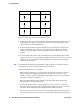
General Operation Seq. Ch. No. Zone Channel 1 1 1 16 17 2 16 1 3 16 1 32 33 48 16 Proceed as follows to select channels using this mode: 1 Enable the direct Channel Select mode by pressing the Channel Select option switch or selecting the “Chan Selct” menu parameter. The alias and sequential number of the current channel are alternately displayed. 2 Select the desired channel using the Up/Down keys or directly enter it using the 0-9 keys (if available).
General Operation the channel it is indicating. For example, if the switch index is pointing to channel 3 and channel 15 of the current zone is being displayed, rotating it to channel 4 selects channel 4 of the current zone. • If the rotary Channel Select switch is enabled, the radio always powers up on the channel it is selecting. If it is disabled, the radio can be programmed to power-up on the last selected or home channel number of the last selected or home zone.
General Operation 3 Press the up/down button to the location (1-16) where you want to store this favorite. The radio will automatically start at the first unprogrammed channel and if all channels are programmed, the radio will start at Channel 1. 4 To store the new channel in to the favorite zone, press the Select button which is on the portables. The radio will then return to its previous zone/channel.
General Operation 3.4.2 Note Low Battery Indication If the radio contains encryption keys and is not programmed for infinite key retention, be sure to reattach a battery within approximately 30 seconds to prevent the loss of these keys (see following). A low-battery condition is indicated by the icon in the display. The battery should be recharged or replaced as soon after this indication appears. Once this indication appears, it stays on until power is cycled.
General Operation Do not expose the charger base to high level RF signals while a battery is being charged because this may cause a charger fuse to blow (especially in the UHF range). Radios programmed for SMARTNET/SmartZone operation, for example, may affiliate while in the charger which causes them to automatically key. Therefore, do not leave radio power on while charging as described above. 3.4.
General Operation 4 Install the included locking screw in the latch tab in the location shown. Figure 3.3 Accessory Connector Install Lock Screw Here Accessory Connector Latch Hook 3.5 Backlight The backlight for the display and option keys can be programmed to automatically turn on when any key is pressed. It then automatically turns off after a programmed delay of 0-7.5 seconds so that battery drain is minimized.
General Operation Keypad Lock and Permanent Lock functions. If this function is not selected, both the front and side panel keys are disabled. The PTT switch is never disabled. • The Channel Selector and Volume controls can be programmed so that they are locked by the Keypad Lock function. • The “Channel Selector Enabled” function can be programmed globally. If this is not selected, the channel selector is always disabled regardless of the Permanent Lockout or Keypad Lock status.
General Operation 3.9 Radio Operating Modes Each selectable channel can be programmed for the conventional (analog or APCO Project 25 digital), SMARTNET/SmartZone, or APCO Project 25 digital trunked operating mode. For example, Zone 1/Channel 1 could be a conventional channel, Zone 1/ Channel 2 a SMARTNET channel, and so on. More information on these modes follows. 3.9.1 Conventional Mode This is a non-trunked operating mode which accesses independent radio channels.
General Operation When a SMARTNET or SmartZone channel is selected or the radio is powered up on one of those channels, it searches for a control channel. Once a control channel is found, the alias (name) of the selected channel is displayed and the radio attempts to register on the radio system.
General Operation 3.9.4.1 Systems A system is a collection of channels or talk groups belonging to the same repeater site. It defines all the parameters and protocol information required to access a site. Up to 16 systems of any type can be programmed. The maximum number of channels assignable to a system is limited to 864. Channels may also be limited by available memory space as described in the following information. 3.9.4.
General Operation 3.10 Radio Tune Test Mode The Radio Tune Test function is used primarily by technical personnel. To enter Radio Tune Test Mode, press Side Button 2 during the interval between the initial display and the completion of the self test. Pressing Side Button 2 after the self test has completed has no noticeable effect on the radio other than its programmed functionality. I.e.
General Operation 3.10.1 RF Test Mode In RF Test Mode, the radio has a set number of frequencies and tests that can be run depending on the radio’s band. The frequencies that can be tested are summarized in Table 3.2 and the test environments are summarized in Table 3.3. Press Side Button 2 to advance to a different test channel, and press Side Button 1 to advance to the next test. In this mode, the display shows the current environment and frequency, “SSSSS: x”.
General Operation 3.10.2 Control Top and Keypad Test Mode Once Control Top and Keypad Test Mode is selected from the menu, all icons are displayed and the LED lights red. Upon release of the emergency button, the radio is in Control Top and Keypad Mode. In this mode, all of the buttons, switches, and knobs on the radio can be tested to determine if they are operating correctly. Performing any event with the radio results in a tone as well as a display of what action took place.
S E C T I O N Radio-wide Features Section 4 4.1 Option Switches Most all the buttons on this radio are programmable as follows: • On the side panel, the three buttons above the PTT switch (see Figure 2.3). • On the top panel, the rotary three-position switch and the orange button (see Figure 2.2). Note For descriptions of the functions controlled by these switches, refer to the section of this manual referenced in the last column of Table 4.1. Table 4.
Radio-wide Features Table 4.
Radio-wide Features Table 4.1 Programmable Option Switch and Menu Mode Functions SMARTNET/ Conventional SmartZone 4.2 P25 Trunking Status X X X Survelliance Mode X X X Text Message X Tone Vol Edit - Alert X X X Tone Vol Edit - Keypress X X X Unit Call X Unprogrammed X X X Zone Select X X X X Feature Enable / Disable One of the function buttons may be programmed to enable/disable certain features.
Radio-wide Features 4.3 Menu Mode Most functions that can be controlled by an option switch can also be controlled by the menu mode. The functions that can be controlled by the menu mode are shown in Table 4.1. Functions can be controlled by both an option switch and a menu parameter if desired. When the menu mode is used, the and switches become dedicated menu mode control switches (see following illustration). The switch is Back/Clear, and the switch is Menu Select/Enter.
Radio-wide Features 4.4 Time-Out Timer The time-out timer disables the transmitter if it is keyed continuously for longer than the programmed time. It can be programmed for 15-225 seconds or it can be disabled by programming 0 seconds. If the transmitter is keyed for longer than the programmed time, the transmitter is disabled, a continuous tone sounds, and “TX Timeout” is displayed. Five seconds before time-out occurs, a warning beep sounds to indicate that time-out is approaching.
Radio-wide Features The new level is flashed in the display as either “Hi Power” or “Low Power”. If selectable power is not permitted on the current channel, “Fixed Low” or “Fixed High” is flashed and no change occurs. The selected power level for a channel or system is permanent until it is manually changed again. The low power mode may be automatically selected during a low battery condition (see Section 3.4.2). 4.7 Alert Tone Select The various alert tones that sound are described in Section 2.5.
Radio-wide Features 4.9 Scanning Scanning monitors the channels in the scan list for messages that the radio is programmed to receive. When a message is detected, scanning stops and the message is received. Shortly after the message is complete, scanning resumes (unless it has been disabled). When a call is received in the scan mode, the alias of the channel on which a call is received (and any other display parameters that may be programmed) are displayed until scanning resumes.
Radio-wide Features 4.9.2 Radio Wide Scanning Radio wide scanning monitors the channels in the pre programmed radio-wide scan list. This scan list can include up to 16 channels of any type and assigned to any zone (see Section 4.10.2). Radio wide scanning is turned on and off by the Radio Wide Scan option switch or menu parameter as follows. If this switch or menu parameter is not programmed, radio wide scanning is not available.
Radio-wide Features 4.9.4.1 Priority Scan Mode When the transmitter is keyed while scanning is enabled, the transmission may occur on various channels as follows. Conventional Operation - Transmissions can be programmed to always occur on the priority, selected, or receive channel (if applicable). Refer to Section 5.10 for more information.
Radio-wide Features 4.10.1 Priority Scan Lists A scan list is simply the channels that are scanned when scanning is enabled. With all operating modes, as many priority scan lists as are required can usually be programmed (up to 256). The only limitation is the available memory. Each scan list can include up to 256 channels/talk groups. More information on selecting and editing priority scan lists follows. Note The selected channel is always scanned. 4.10.1.
Radio-wide Features If the Scan (List) Select option switch or menu parameter is programmed, the list that is selected by all talk and announcement groups in the current system can be temporarily changed by the user as follows. “No List” (scanning disabled) or “Programmed” (default list) can also be selected if desired. The temporary programmed scan list is retained through radio power down.
Radio-wide Features With conventional channels only, if the selected scan list is programmed with fixed priority channel(s), the next press of makes the current channel the priority channel indicated by . If dual priority channels are used, pressing again makes it the second priority channel indicated by 2 . Then pressing again takes the channel out of the scan list. Refer to Sections 5.10.2 and 6.11.1 for more information on priority channel sampling.
S E C T I O N Conventional Mode Features Section 5 An overview of the conventional operating mode is located in Section 3.9.1. The following information describes the features unique to analog and digital (Project 25) conventional operation. Refer to the preceding “Radio Wide Features” (Section 4) for information on features common to all operating modes. 5.
Conventional Mode Features 5.1.2 Manual Channel Monitoring The automatic monitoring just described may occasionally disable the transmitter when the channel is not in use, such as if the repeater has extended hang time. In this case, you may not want to use automatic monitoring, but monitor the channel manually as follows: Busy Indicator - With scanning disabled, note if the multi-function indicator on the front panel is steady green.
Conventional Mode Features 5.3 Busy Channel Lockout The Busy Channel Lockout feature (also called Transmit Disable on Busy) automatically disables the transmitter if the channel is busy when the PTT switch is pressed. When the transmitter is disabled by this feature, “Busy” is displayed, a busy tone sounds, and the transmitter is disabled. The Busy Channel Lockout feature can be programmed to operate as follows. Each conventional channel can be programmed differently.
Conventional Mode Features 5.4.1 Call Guard Squelch Enable / Disable The Normal/Selective option switch or menu parameter (if programmed) can be used to disable receive Call Guard squelch on analog channels or talk group ID code detection on P25 channels. When selective squelch is disabled, “Sq Normal” is flashed in the display, and when it is enabled, “Sq Select” is flashed. When “Normal” is selected, the receiver unsquelches only if a carrier is detected.
Conventional Mode Features 5.4.4 Selective Squelch Code Select (CTCSS / DCS / NAC) This feature allows the normal transmit and receive Call Guard (CTCSS/DCS/NAC) programming to be temporarily overridden with a code selected from a pre programmed list. It is available if the Squelch Select List option switch or menu parameter and a CTCSS/NAC code list have been programmed. Note Call Guard codes can be permanently reprogrammed by keypad programming described in Section 5.15.
Conventional Mode Features 5.5 Penalty Timer A penalty timer may be programmed on conventional systems to prevent transmissions for the programmed time after the time-out timer disables the transmitter (see Section 4.4). The penalty timer can be programmed for the same times as the time-out timer, and timing starts when the PTT switch is released. If the PTT switch is pressed while the timer is running the timer stops, and continues when the PTT switch is released.
Conventional Mode Features A function buttons can be programmed to the “Repeater Talkaround” function. With a button programmed as “Repeater Talkaround”, the user can press this button while on any conventional frequency, shifting the radio from operation through a repeater, to simplex operation on the repeater transmit frequency. With a “Repeater Talkaround” button enabled, there is no restriction as to which channels the user can transmit (in simplex mode) on the repeater transmit frequency.
Conventional Mode Features In the P25 conventional mode, a special P25 emergency data transmission is sent, and in the conventional analog mode, an DTMF emergency ID is sent. This ID is programmed on the Conventional Per System screen. Refer to Section 5.12.3 for information on MDC1200 Emergency Alert. For an Emergency Alarm: • The DTMF Emergency ID is sent. • The MDC ID is sent with the emergency bit set. • The Five Tone ID is sent with the fifth tone being status type emergency.
Conventional Mode Features If an emergency call is received by the radio on the selected channel, the emergency alarm ACK tone will sound (5 consecutive tones), and the Emergency Received message will display, followed by the unit ID of the emergency radio. If any other emergency calls are made after this initial one using a different radio, the tone will not sound, but the unit ID will be updated to reflect the most recent emergency call.
Conventional Mode Features 2 If the preceding Emergency Hot Mic feature is enabled, the call is automatically transmitted without pressing the PTT switch. If it is disabled, press the PTT switch and begin speaking as with a standard call. If the channel is changed, operation continues on the new channel in the emergency mode. 3 With analog calls, subsequent presses of the PTT switch cause the DTMF emergency ID to be sent according to the ANI programming (if DTMF ANI is enabled on the channel).
Conventional Mode Features Priority/Tx Selected - Priority sampling occurs and the priority channel or channels are those programmed in the selected scan list. The radio transmits on the selected channel. Priority/Tx Priority (1) - Priority sampling occurs and the priority channel or channels are those programmed in the selected scan list. The radio transmits on the priority (1) channel. Priority (1) on Selected - The priority (1) channel is always the selected channel.
Conventional Mode Features Priority channel sampling occurs only with conventional priority scanning. It does not occur with radio wide scanning, when listening to any type of SMARTNET/SmartZone/ P25 trunked call, encrypted call, or when transmitting (see preceding note). A series of “ticks” may be heard when the priority channel is sampled while listening to a message on some other conventional channel.
Conventional Mode Features 5.11 Standard Conventional Calls Standard conventional calls are placed to other radio units monitoring the selected channel. The proper coded Call Guard squelch tone or code or P25 NAC may need to be transmitted by your radio for them to receive a call (see Sections 5.4 and 5.14.3). 5.11.1 Placing a Standard Conventional Call 1 Turn power on and set the volume as described in Section 3.1. Select the channel programmed for the radio you want to call as described in Section 3.3.
Conventional Mode Features Three features use analog signaling: • Pre and Post ANI • Emergency Alarm • RTT 5.12.1 DTMF / ANI Signaling Dual Tone Multi-Frequency (DTMF) tones can be generated for Automatic Number Identification (ANI) and other purposes on conventional analog channels. One of the following options may be enabled on each channel: Pre-Tx ANI - A pre programmed ANI sequence is automatically sent each time the PTT switch is pressed.
Conventional Mode Features MDC1200 ANI - Both pre and post ANI are supported.
Conventional Mode Features 5.13 Clone Mode The Clone feature enables one radio to program another with identical information. The PC Configure programming software is not required. Other requirements are as follows: • The Clone menu parameter must be enabled in the master (sending) radio. This parameter is not required with the slave (receiving) radio. • The master and slave radios must be identical models (same frequency range and options).
Conventional Mode Features 3 With wireless cloning, a screen is then displayed for entering the P25 Unit ID of the destination (slave) radio. Enter this ID using the keypad (or the Up/Down keys) and . 4 The clone mode “Zone” or “Complete” is then selected. Select the desired mode. Operation is as follows: Zone - This mode allows channel information for only the selected zone to be transferred. Information programmed on the Global, Radio Wide, and Per System screens is not changed.
Conventional Mode Features 5.14.3 Network Access Code Project 25 conventional channels also use a NAC (Network Access Code) to control which calls are received on a channel. The NAC can be 0-4095, and each transmit and receive channel can be programmed for a different code. Other operation, such as monitoring before transmitting, is similar to that of analog channels. NAC (and talk group ID) detect can be disabled by the monitor mode described in Section 5.2. 5.14.
Conventional Mode Features 5.14.5 P25 Unit Calls Unit Calls (also called Individual Calls) can be placed to a specific radio on a Project 25 channel if the Unit Call option switch or menu parameter is programmed. Only the individual ID of the target radio is sent (a talk group ID is not sent). The radios that can be called are pre programmed in the Unit Call list. To receive a Unit Call, the RF channel of the call must be selected or scanned and the correct NAC and unit ID must be detected.
Conventional Mode Features Both limited and DTMF keypad models can place telephone calls by recalling the telephone number from a pre programmed list as just described. However, only DTMF keypad models can directly dial telephone numbers using the keypad. 5.14.6.1 Access / De-Access Codes P25 conventional telephone calls use an access code to access the system when placing a telephone call, and a de-access code to terminate the call when it is finished.
Conventional Mode Features 5 Press the PTT switch to talk and release it to listen. Since the radio operates half duplex, it is not possible to talk and listen at the same time. 6 When the telephone call is finished or if it could not be completed for some reason, end it by pressing the Phone option key or key. This sends the de-access code which tells the system that the call is finished and that the repeater can be released. 5.14.6.
Conventional Mode Features 1 With a P25 conventional channel selected, momentarily press the Call Alert option switch or select that menu parameter. The alias of the last ID called is displayed. 2 If required, press the Up/Down switch to display the desired radio. The alias of each number is displayed. 3 Press the PTT switch or the key and one of the following occur: - If five beeps sound, the system received the page and the paged radio is on the air and received it.
Conventional Mode Features 2 To change the current status, press the Up/Down switch until the desired status is displayed. Then to send the status, press the (Select) switch or momentarily press the PTT switch. One of the following events then occurs: - If five beeps sound and “Ack Rcvd” is displayed, the status was received and acknowledged by the system. - If after five tries the message is not acknowledged, a tone sounds and “No Ack” is displayed.
Conventional Mode Features Keypad programming allows conventional channel parameters such as the transmit and receive frequency, Call Guard squelch code, and encryption key to be changed. In addition, several conventional mode timers can be changed. It cannot be used to reprogram disabled channels or any SMARTNET/SmartZone/P25 Trunked information. Figure 5.
Conventional Mode Features Press the (Select) key to select a highlighted parameter, and press the key from one of the main menus to exit keypad programming. Pressing it in the other menus returns to the previous menu. The Up/Down switch is also used in several menus to scroll through available selections. Additional information on this parameters is located in the following sections. 5.15.
Conventional Mode Features 5.15.5 System Parameters Note If “Password” is briefly displayed when attempting to select a parameter, see Section 5.15.2. The “Sys Parms” menu parameter selects the conventional mode timers to be reprogrammed (see following). Press the switch to select the “Sys Parms” parameter and then press the Up/Down switch to display the desired parameter. Then press the switch again to select it. Scan Timer - Selects the Scan Hold timer.
Conventional Mode Features Sq Adj (Analog Only) - Changes the preset squelch setting on that channel. The default setting is “0” and values of –7 to +7 can be selected. Increasing this setting toward +7 causes the squelch to open sooner so that weaker signals can be received, and decreasing it toward –7 causes the opposite to occur.
Conventional Mode Features code type (CTCSS analog or DCS digital). Then press to select it and enter the code number similar to programming a channel frequency as just described. Rx Code - Selects the receive codes the same as Tx Code above. 5.15.6.2 NAC Squelch Control (Project 25 Channel) TX NAC - Programs the transmit Network Access Code (NAC) which can be any number from 0-4095. With later models, this number is displayed in hexadecimal from 000-FFF.
S E C T I O N SMARTNET / SmartZone / P25 Trunked Features Section 6 An overview of the SMARTNET®/SmartZone® and P25 Trunked operating modes is located in Section 3.9. The following information describes the features unique to these modes of operation. Refer to the “Radio Wide Features” section starting on Page 3-1 for information on features common to all operating modes. 6.1 Analog and Digital Operation Either analog or digital operation can be selected for communication on traffic channels.
SMARTNET / SmartZone / P25 Trunked Features 6.3 Standard Group Calls Standard group calls may be placed to another radio, group of radios, or a dispatcher, depending on programming. Most calls are probably this type. Proceed as follows to place and receive group calls. 6.3.1 Placing a Standard Group Call 1 Turn power on and set the volume as described in Section 3.1. Select the channel programmed for the talk group you want to call (see Section 3.3).
SMARTNET / SmartZone / P25 Trunked Features 6.3.2 Receiving a Standard Group Call Calls are received on only the talk group and/or announcement group programmed for the selected channel (with scanning disabled). When the selected channel is programmed with both Talk and Announcement groups, only the Talk and Announcement group IDs are detected. Other IDs in the Announcement group are detected only if no talk group is programmed.
SMARTNET / SmartZone / P25 Trunked Features Both limited and DTMF keypad models can be programmed to recall the unit IDs from a preprogrammed list. However, only DTMF keypad models can be programmed to directly dial unit IDs. 6.4.1 Placing an Enhanced Private Conversation Call To recall from a list: 1 Momentarily press the Private Call option key or select that menu parameter and the in alias of the last called radio is displayed. The private call mode is indicated by the display.
SMARTNET / SmartZone / P25 Trunked Features - If your radio or the called radio is inhibited or not programmed to make this type of call or for the requested secure mode, “Rspns Only” is displayed and an alert tone sounds. - If your radio does not have the proper encryption key, “Keyfail” is displayed and the call must be made in the clear mode by pressing the Clear/Secure option key (if strapped to switchable). Otherwise, load the correct key.
SMARTNET / SmartZone / P25 Trunked Features - If the radio system is busy, four low tones sound and “Busy” is displayed. When the system is no longer busy, the call back tone (four beeps) is heard and the channel is automatically acquired. Press the PTT switch to continue the call.
SMARTNET / SmartZone / P25 Trunked Features 6.5 Telephone Calls The telephone call feature allows telephone calls to be placed and received over the public telephone system using your radio. Telephone calls are programmed to operate in one of the following modes: • Disabled • Answer-only capability • List only - Telephone numbers can be selected from a pre programmed list only (direct entry using the keypad is not allowed).
SMARTNET / SmartZone / P25 Trunked Features 3 Press and release the PTT switch and “Dialing” is displayed. Events that may occur are as follows: - If the access is successful, a dial tone sounds and the dialed number is displayed and sent. Either ringing or a busy signal is then heard as with a standard telephone call. When the called party answers, press the PTT switch to talk and release it to listen (since the radio is half-duplex, it is not possible to talk and listen at the same time).
SMARTNET / SmartZone / P25 Trunked Features 6.6 Call Alert The Call Alert™ feature allows pages to be sent and received. With SMARTNET/ SmartZone operation, either the Enhanced Private Conversation™ or Standard Private Conversation mode may be programmed depending on the capabilities of the radio system. With P25 Trunked operation, operation is similar to the enhanced mode. 6.6.1 Answering a Page 1 When a page is received, five beeps sound and “Page Rcvd” is displayed.
SMARTNET / SmartZone / P25 Trunked Features 3 Press the PTT switch or the key and one of the following occur: - If five beeps sound, the system received the page and the paged radio is on the air and received it. The page mode is automatically exited. - If the system received the page but the called radio is not on the air, a single beep sounds and “No Ack” is displayed 6 seconds after the PTT switch is pressed. Auto exit then occurs. 6.
SMARTNET / SmartZone / P25 Trunked Features 2 To change the current status, press the Up/Down switch until the desired status is displayed. Then to send the status, press the (Select) switch or momentarily press the PTT switch. One of the following events then occurs: - If five beeps sound and “Ack Rcvd” is displayed, the status was received and acknowledged by the system. - If after five tries the message is not acknowledged, a tone sounds and “No Ack” is displayed. Note 6.
SMARTNET / SmartZone / P25 Trunked Features 1 If required, press the Emergency option switch or select that menu parameter. The radio then automatically transmits the emergency alarm. 2 Either Normal or Silent operation can be programmed. With the Normal mode, the red LED lights, the emergency tone sounds, and “EMERGENCY” flashes in the display. This indication continues to flash until the alarm mode is ended (see Step 4). If silent programmed or the Surveillance mode is selected (see Section 4.
SMARTNET / SmartZone / P25 Trunked Features 6.9.3 Emergency Calls An emergency call urgently requests access to a voice channel (an emergency tone usually does not sound at the console unless the call is combined with an Emergency Alarm). An emergency call is placed by pressing the PTT switch after pressing the Emergency option button or selecting the Emergency menu parameter.
SMARTNET / SmartZone / P25 Trunked Features options. If “No Receive Activity During Emergency” is programmed, receive audio and the front panel LED are disabled in the receive mode. 5 To exit this mode, cycle radio power or press and hold the Emergency switch. Note Communications between the radio with the emergency and the dispatcher are closed.
SMARTNET / SmartZone / P25 Trunked Features • Scanning is turned on and off by the Scan option switch or menu parameter. Talk groups (channels) can be programmed so that scanning automatically starts when the talk group is selected (Autoscan). • When responding to calls in the scan mode, the programming of the Talkback Scan parameter determines if a response always occurs on the talk group of the call (Active Group) or the Selected Group if they are different.
SMARTNET / SmartZone / P25 Trunked Features One talk group in the scan list can be designated a priority talk group by programming or it can be the selected talk group. When scanning, messages on a non-priority talk group are interrupted by messages on the priority talk group. Priority scanning must also be supported at the system level for it to occur as programmed in the radio. P25 trunking supports dual priority scan, therefore two priority talk groups can be selected.
SMARTNET / SmartZone / P25 Trunked Features 6.13 SmartZone and P25 Trunked Unique Features P25 Trunked and SmartZone modes can provide access to single or multi-site systems. The P25 Trunked mode can provide access to a single trunked site or roaming between several trunked sites. 6.13.1 Busy Override The busy override feature is enabled at the system level by the system manager and is not a programmable radio feature.
SMARTNET / SmartZone / P25 Trunked Features 6.13.3 Determining Current Site and Searching For New Site To display the RSSI level of the current site, press the Site Search option switch or select that menu parameter. The display then indicates the current site number as “Site xx” and the RSSI level as “RSSI xx”. This mode is then automatically exited. To scroll through the other programmed sites, press and hold the Site Search option switch while “Site xx” or “RSSI xx” is displayed.
SMARTNET / SmartZone / P25 Trunked Features The result of this operation is that all radios with the same programmed home site are forced to the home site to communicate which ensures that they can continue to communicate. If the home site is not available, the Out-of-Range condition tells the user to attempt communication on another system or by some other means. 6.13.
SMARTNET / SmartZone / P25 Trunked Features 6.13.7.3 P25 Wide Area Scan A feature called Wide Area Scan can be programmed to minimize the problem just outlined. This feature is programmed on the Talk Group list screen selected on the P25 System screen. When Wide Area Scan is selected, talk group site preferences are no longer available. However, System Site Preference lists can still be used. The Wide Area Scan feature functions as follows: 1 Assume TG1 is selected.
S E C T I O N Miscellaneous Section 7 7.1 Error Messages The following are definitions of the various error messages that may be displayed. Aff Failed - A group affiliation attempt has received a Failed response from the system. The precise reason for a Failed response is manufacturer dependent. Aff Deny - A group affiliation attempt has received a Denied response from the system. The precise reason for a Denied response is manufacturer dependent.
Miscellaneous Busy - A call has been attempted and the system has responded that no channels are available for assignment. Busy Tmout - The radio previously received a busy response from the system and it has not received a channel grant before the busy time-out timer has expired Disabled - The selected channel is disabled. Clear Only - The selected channel or group is strapped clear only and a secure call can not be made.
Miscellaneous Kypd Lockd - The keypad lock function is active and key presses are not accepted in this mode. Kset Fail - The encryption key set chosen by the user is not valid. List Only - Direct entry of a unit ID or phone number is disabled. Locked - A selector lock command has been received and zone and channel changes are not accepted. Lost Signl - Signal from the infrastructure has been lost during an interconnect call.
Miscellaneous VOLTAGE HI - The input voltage to the mobile is too high. VOLTAGE LO - The input voltage to the mobile is too low. Write Fail - The radio is unable to write to the EEPROM. 7.2 System Operator Programming As noted several times in this manual, programming determines the availability and specific operation of many features. This usually refers to the programming performed by the PC Configure programmer when the radio was set up, not to any programming a user can perform.
Miscellaneous 7.5 Licensing A government license is usually required to operate this radio on the air. 7.6 Radio Service If the radio is not responding to any key presses, the keypad may be locked. Refer to Section 3.6 for more information. If “Password” is briefly displayed when power is turned on and you are prompted to enter a password, the Power-Up Password feature is enabled. Refer to Section 3.2 for more information.
Miscellaneous 7-6 5100 ES Models II/III Portable Radio Operating Manual March 2008
S E C T I O N Determining Available Options Section 8 This manual describes the operation of all features that are currently available for the 51xx ES radio. However, many of these features are optional and therefore may not be available in your radio. For example, Project 25 trunked operation is optional and may not be available. Model III radios have the DTMF keypad, but the Model II radios do not have this feature.
Determining Available Options Ο SmartZone analog operation Ο Digital SMARTNET/SmartZone Feature Options Ο Keypad programming (Federal Government users only) Ο 864 channels/talk groups Ο DTMF Keypad support Ο Zonefail site lock Currently, the only operating mode that is standard with all models is the conventional analog mode. Other variables such as frequency range are hardware dependent instead of software dependent. The capability exists to upgrade radios in the field with new features.
S E C T I O N Passwords Section 9 The following passwords may be set: • Four Power-On (User x) Passwords • Download and Upload Passwords • Master Password • Zone Passwords 9.1 Password Descriptions Passwords are described below: 9.1.1 User (Power-On) Passwords When a User Password is enabled, it must be entered each time radio power is turned on. Up to four different User Passwords (User 1/User 2/User 3/User 4) can be programmed. Currently, the same radio features are enabled for each.
Passwords 9.1.2 Download/Upload Passwords Separate Download (write) and Upload (read) passwords can be programmed to prevent unauthorized downloading or uploading of radio programming parameters. When one or both of these passwords are used, the proper password must be entered to perform the operation. A “User” password is not required to upload or download parameters. 9.1.3 Master Password The Master Password overrides all the preceding passwords.
Passwords Password data is transferred and stored in an encrypted format for security purposes. In addition, actual passwords are never displayed. They are always indicated by eight asterisks (********). Therefore, it is not possible to determine what passwords are in a radio using the PC Configure software. Passwords must be 1-8 characters in length and consist of the numbers 0-9. Zeros are valid characters in any location, even as leading characters.
Passwords 9-4 5100 ES Models II/III Portable Radio Operating Manual March 2008
S E C T I O N Secure Communication (Encryption) Section 10 This radio may be equipped to provide secure communication on some or all channels. This feature encrypts the voice so that it can be understood only by someone using a radio equipped with a similar encryption device and encryption codes. When a secure call is received, the LED flashes Red and is indicated in the display.
Secure Communication (Encryption) 10.1.2 AES (Advanced Encryption Standard) An encryption standard called AES is replacing DES-OFB encryption on digital (P25) channels. It uses a 128-, 192-, or 256-bit encryption key instead of the 64-bit key used with DES. EFJohnson radios currently support only 256-bit AES keys. The type of encryption (DES or AES) is determined by the type of encryption key that is loaded.
Secure Communication (Encryption) If an attempt is made to transmit a secure message without loading the corresponding key, “Keyfail” is displayed. The message must then be transmitted in the clear mode (this is possible only if the channel is strapped to “switchable”) or the key must be loaded. 10.2.1 Key and Algorithm IDs Each encryption key is programmed with a Key ID (also called Logical ID). This ID plus the algorithm ID (ALGID) is transmitted in the message on digital channels.
Secure Communication (Encryption) Number), typically from 0-4095. The Keys Table must then be programmed to link channel PIDs to a specific SLN. The use of this type of indirect linking allows keysets and key IDs to be changed through OTAR while keeping the mapping from the channel or talk group the same. For example, as shown in Figure 10.1, PID 4 selects SLN 24 which selects key slot 24 in both keysets. This slot contains Key ID 69 in Keyset 1 and Key ID 91 in Keyset 2.
Secure Communication (Encryption) 10.2.5 Encryption Key Erase A Key Erase menu item can be programmed that allows the user to permanently erase all stored keys. If OTAR TEK and KEK keys are stored, all keys of both types are erased. This function can be used to ensure that unauthorized encrypted calls can no longer be placed or received by a radio. 10.2.6 Encryption Icon Operation Basically, the encryption icon is on continuously whenever a secure call is received or transmitted.
Secure Communication (Encryption) The radio can be programmed to ignore the “Clear” or “Secure” switch setting. These preceding indications then do not occur and transmissions always occur in the strapped mode. Note If all channels/talk groups are strapped clear or secure and no Clear/Secure option switch or menu parameter is programmed, this parameter must always be selected (see following).
Secure Communication (Encryption) 10.4 Over-The-Air Rekeying (OTAR) Over-The Air-Rekeying (OTAR) is the process of sending encryption keys and related key management messages over-the-air to specific radios. The advantage of OTAR is that it allows these keys to be quickly and conveniently updated when necessary. It is no longer necessary to periodically travel to the radio location or bring the radio into a maintenance facility to load new keys.
Secure Communication (Encryption) While the active keyset is usually selected by the Key Management Facility, it can also be selected by the radio user if the KY CHG option switch is programmed. In this fashion, two keysets can be used even if OTAR is not being used. Note that the radio must be in SLN mode (see Section 10.2.2) to make use of keysets. KEKs are always placed in Keyset 255, and are always considered to be active. The valid SLN range for Keyset 255 is 61440 through 65535.
Secure Communication (Encryption) The KMF performs OTAR functions by exchanging Key Management Messages (KMMs) with the radios. Both the KMF and radio can originate messages.
Secure Communication (Encryption) 10.4.5 Definitions Algorithm - Refers to the specific encryption standard (DES or AES) that is used to encrypt a message. Each standard uses different calculations to perform the encryption (see Section 10.1). Algorithm ID (ALGID) - Identifies the algorithm (DES or AES) used to encrypt a message. This ID and the Key ID are transmitted with each non-analog message to uniquely identify the key being used. Black - Refers to information that is encrypted.
Secure Communication (Encryption) Key Management Message (KMM) - These are the messages composed by the KMF to send encryption information to subscriber units through the keyloader or OTAR. KMMs are themselves encrypted using two layers of encryption: inner and outer. The inner layer of encryption uses a KEK and the outer layer uses a TEK. Additional security measures contained within KMMs include a Message Number (MN) and a Message Authentication Code (MAC).
Secure Communication (Encryption) Traffic Encryption Key (TEK) - A key used to encrypt voice or data. The other type of key is the Key Encryption Key (KEK) which is used to encrypt keys contained in Key Management Messages. TEKs can be either the AES or DES type. Unique Key Encryption Key (UKEK) - A KEK unique to a particular subscriber unit. Refer to “KEK” for more information. These keys can be either the AES or DES type.
Secure Communication (Encryption) MNP (Message Number Period) - Load the proper message number period into the radio (typically 1000). Refer to Section 10.4.4 for more information. Verify that the above information was properly stored in the radio by viewing it using the keyloader. 10.5 Radio OTAR Capabilities The OTAR capabilities of the SEM equipped 5100 ES portable are as follows. • Keysets - Up to three keysets are used and it is assumed all three are always present.
Secure Communication (Encryption) NO SERVICE 0x17 REKEY ACK 0x1D OTAR REGISTRATION 0x25 OTAR REGISTARTION RESPONSE 0x26 REKEY 0x1E UNABLE TO DECRYPT 0x27 WARM START 0x20 ZEROIZE 0x21 ZEROIZE RESPONSE 0x22 10.5.2 OTAR Option Switches The following additional option switches can be programmed with the 5100 ES portable to control OTAR functions. They are also available as 5100 ES menu parameters unless noted otherwise. Change Keyset - Toggles the active keyset between Keyset 1 and Keyset 2.
Secure Communication (Encryption) Erase Keys - Erases all keys in the radio the same as the Erase Keys option switch described in the preceding section. (Can be option switch or menu parameter.) 10.6 Over the Air Programming OTAP is an “Over the Air” programming feature for the subscriber parameter (code plug) files. Using the OTAP feature, parameter files can be updated and changed in the field, eliminating the need to take the radio out of service to perform the updates.
Secure Communication (Encryption) Note The radio will reset after a successful download in this mode, but the previous radio profile will remain in use until the radio user or PC Configure operator activates the OTAP parameter. If the OTAP procedure is not successful, the radio will reboot and return to normal operating mode with the current parameters. 10.6.2 OTAP Transfer Times Larger files tie up the radio for a long time.
S E C T I O N Service Information Section 11 This section describes how to obtain authorized service for the 5300 ES Series mobile radio. 11.1 Product Warranty The warranty statement for this equipment is available from your product supplier or from: Warranty Department EFJohnson 8050 Jetstar # 175 Irving, TX 75063 This information may also be requested from the Warranty Department by phone at the numbers listed in Section 11.4.
Service Information To register EFJohnson products online, visit www.EFJohnson.com. Click the link that says Register your EFJohnson products online or go to http://www.efjohnson.com/ WarrantyRegistration.asp. Then, follow the instructions to register your products. 11.3 Telephone Technical Support Technical support personnel can help resolve many issues over the telephone, such as display, volume, software, programming. Please refer to Section 11.
Service Information Customer Service Department EFJohnson 8050 Jetstar # 175 Irving, TX 75063 11.5 Returns for Repairs Before returning equipment for repair, contact the EFJohnson Customer Service Department as described in the preceding section. They may be able to suggest a solution to the problem, making return of the equipment unnecessary. Repair service is normally available through local authorized EFJohnson land mobile radio service centers.
Service Information 11.6 Replacement Parts Replacement parts can be ordered directly from the Service Parts Department. To order parts by phone, dial the toll-free number as described in Section 11.4. When ordering, please supply the part number and quantity of each part ordered. EFJohnson dealers also need to give their account number. If there is uncertainty about the part number, include the designator (C512, for example) and the model number of the equipment the part is from.
Index A Accessory Connector . . . . . . . . . . . . . . . . . . . . . . . . . . . .2-5 AES Encryption . . . . . . . . . . . . . . . . . . . . . . . . . . . . . . . .10-2 Alert Tones . . . . . . . . . . . . . . . . . . . . . . . . . . . . . . . . . . . .4-6 Algorithm . . . . . . . . . . . . . . . . . . . . . . . . . . . . . . . . . . . .10-10 Algorithm ID . . . . . . . . . . . . . . . . . . . . . . . . . . . . . . . . . .10-10 Analog and Digital Operation . . . . . . . . . . . . . . . . . . . . . . .
Index (continued) Hot Mic . . . . . . . . . . . . . . . . . . . . . . . . . . . . . . . . . . 5-9, 6-13 Monitor Mode . . . . . . . . . . . . . . . . . . . . . . . . . . . . . . . . . . 5-2 Monitoring Before Transmitting . . . . . . . . . . . . . . . . . . . . . 5-1 I Indicator Priority Channel . . . . . . . . . . . . . . . . . . . . . . . . . . . .5-11 Top Panel . . . . . . . . . . . . . . . . . . . . . . . . . . . . . . . . .2-3 Individual Calls . . . . . . . . . . . . . . . . . . . . . . . . . . . . . .
Index (continued) Squelch Select List . . . . . . . . . . . . . . . . . . . . . . . . . .5-5 Status . . . . . . . . . . . . . . . . . . . . . . . . . . . . . . 5-22, 6-10 Surveillance Mode . . . . . . . . . . . . . . . . . . . . . . . . . . .4-6 Talk Group Select . . . . . . . . . . . . . . . . . . . . . . . . . .5-18 Tone Volume . . . . . . . . . . . . . . . . . . . . . . . . . . . . . . .4-6 Unit Call . . . . . . . . . . . . . . . . . . . . . . . . . . . . . 5-19, 5-21 Volume Up/Down . . . . . . . . . . .
Index (continued) Systems . . . . . . . . . . . . . . . . . . . . . . . . . . . . . . . . . . . . . .3-15 T Talkaround Enable/Disable . . . . . . . . . . . . . . . . . . . . . . . .5-7 TEK . . . . . . . . . . . . . . . . . . . . . . . . . . . . . . . . . . . . . . . .10-12 Telephone Calls . . . . . . . . . . . . . . . . . . . . . . . . . . . . . . . . .6-7 Telephone Calls) . . . . . . . . . . . . . . . . . . . . . . . . . . . 5-20, 6-7 TG on Rx . . . . . . . . . . . . . . . . . . . . . . . . . . . . . . .