
Service manual


POWER SUPPLIES
9-2
March 2000
Part No. 001-3139-502
9.6 VOLTAGE ADJUSTMENTS
9.6.1 -555 SUPPLY
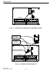
See Figure 9-5 for location of components and
Table 9-2 for wire connections.
1. Connect a voltmeter to U1, pin 76 on an RVM (DO
NOT use an extender card).
2. Adjust the +5V pot on the power supply for a read-
ing of 5.1V.
3. If +5.1V cannot be obtained, change R84 to a 5.6k
ohm 1/4W resistor.
9.6.2 REDUNDANT SUPPLY ADJUSTMENTS
See Figure 9-5 for location of components and
Table 9-2 for wire connections.
1. Remove the AC voltage to one of the supplies.
2. Connect a voltmeter to U1, pin 76 on an RVM (DO
NOT use an extender card).
3. Adjust the +5V pot for a reading of 5.1V. (If +5.1V
cannot be obtained, change R84 to a 5.1k ohm 1/4W
resistor.)
4. Connect a voltmeter to output of CR3 and verify
that the -5V line is -4.8V to -5.2V. (If not, make
R68 lower to raise voltage.)
5. Remove the AC voltage to the adjusted supply and
connect AC voltage to the other power supply.
6. Connect a voltmeter to U1, pin 76 on an RVM (DO
NOT use an extender card).
7. Adjust the +5V pot for a reading of 5.1V. (If +5.1V
cannot be obtained, change R84 to a 5.1k ohm 1/4W
resistor.)
8. Connect a voltmeter to output of CR3 and verify
that the -5V line is -4.8V to -5.2V. (If not, make
R68 lower to raise voltage.)
9.7 RECEIVER SITE REDUNDANT KIT INSTAL-
LATION
1. Remove connector J1 from the -491 board (see Fig-
ure 9-1).
2. Cut connectors off Challenger power supplies.
3. Install a .250 tab receptacle with heat shrink onto
each Challenger power supply wire.
4. On the -491 board, install the Red #12 wire into hole
connected to fuse.
5. Install .250 tab receptacle and heat shrink to other
end of the wire.
6. Install the U-shaped connector to ground hole on
the -491 board with hardware provided and solder
to board.
7. Install diode onto -490 shelf using hardware
provided.
8. Connect the Red wires of the Challenger supplies to
the inputs to the diode.
9. Connect the Red #12 wire from the -491 board to
the output of the diode.
10.Connect the ground wires from the Challenger sup-
plies to the U-shaped connector on the -491 board.
11.Two green LEDs are provided for power supply
operation indicators. Early shelves do not have
holes in the front panel and must be drilled to
accommodate these LEDs (see Figure 9-2 for wir-
ing details).
Table 9-2 POWER SUPPLY CONNECTIONS
TB1 Wire
No.
Colo
r
From
Term 1
Term 2
Term 3
W1
W1
W1
Blk
Wht
Grn
AC (Hot)
AC (Ntrl)
AC (Gnd)
Line
Line
Line
TB2
Term 1
Term 2
Term 3
Term 4
Term 5
Term 6
Term 7
Term 8
Term 9
W1
W2
W6
NC
W7
W4
W5
W3
W8
Red
Red
Blu
Blu
Blu
Wht
Grn
Blu
+5V
+5V
Gnd
Gnd
+12V
-12V
-5V
Gnd
F1
F1
Gnd
Gnd
F3
F4
F2
Gnd