OPERATOR’S MANUAL Multi-Net II ® NETWORK MANAGEMENT FOR SIMULCAST Part No. 002-0690-201 6-97 Printed in U.S.A.
Multi-Net® II Network Management For Simulcast Operator’s Manual Copyright© 1997 by E.F. Johnson Company E.F. Johnson Company designs and manufactures two-way radio equipment to serve a wide variety of communications needs. E.F. Johnson Company produces equipment for the mobile telephone and land mobile radio services which include business, industrial, government, public safety, and personal users.
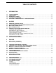
TABLE OF CONTENTS 1 INTRODUCTION 1.1 1.2 1.3 1.4 1.5 SCOPE OF MANUAL . . . . . . . . . . . . . . . . . . . . . . . . . . . . . . . . . . . . . . . . . . . . . . . . . . . . . . . . . . . . . . . . . . . . . . . . .1-1 CONVENTIONS . . . . . . . . . . . . . . . . . . . . . . . . . . . . . . . . . . . . . . . . . . . . . . . . . . . . . . . . . . . . . . . . . . . . . . . . . . . . . .1-1 DEFINITION OF TERMS . . . . . . . . . . . . . . . . . . . . . . . . . . . . . . . . . . . . . . . . . . . . . . . . . .
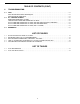
TABLE OF CONTENTS (CONT.) 6 TROUBLESHOOTING 6.1 6.3 PING . . . . . . . . . . . . . . . . . . . . . . . . . . . . . . . . . . . . . . . . . . . . . . . . . . . . . . . . . . . . . . . . . . . . . . . . . . . . . . . . . . . . . . . PING TROUBLESHOOTING TECHNIQUES . . . . . . . . . . . . . . . . . . . . . . . . . . . . . . . . . . . . . . . . . . . . . . . . . . . . . . PING PROGRAM OPERATION. . . . . . . . . . . . . . . . . . . . . . . . . . . . . . . . . . . . . . . . . . . . . . . . . . . . . . . . . .
INTRODUCTION SECTION 1 INTRODUCTION 1.1 SCOPE OF MANUAL Multi-Net System - A trunked radio system that uses E.F. Johnson Multi-Net signaling. Other types of signaling can also be used. A Multi-Net system can be one site or multi-site. Each site uses a different set of channels and radios can be trunked between sites. This manual covers the functions of HP OpenView and the E.F. Johnson application that are available when logged on with the operator password.
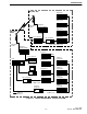
INTRODUCTION 1.4 STARTING THE PROGRAM microwave link that carries other information between sites. Within a site, network components capable of TCP/IP are connected with 10BaseT Ethernet®. The site/channel computers are also connected by a serial link to MBCs (Message Bridge Cards) in the repeaters and channel controllers. E.F. Johnson proprietary software is used to communicate between the computer and MBC; then, the computers pass the information via TCP/IP to the host computer. 1.
INTRODUCTION Rem ote Site Repeater 1 IRDB Repeater 2 Microwave Cable Intraplex Channel Bank Repeater 3 Central Site RS-449 Cisco Router Site Computer Microwave Cable Repeater n Serial Link to MBC Card Intraplex Channel Bank Repeater 1 IRDB RS-449 Cisco Router Channel Controller 1 Hub Repeater 2 IRDB Host Computer Site Computer Repeater 3 Channel Controller 2 Repeater n Channel Controller 3 Serial Link to MBC Card Channel Controller n Channel Computer 10BaseT Ethernet Serial Link to M
INTRODUCTION June 1997 Part No.
ALARMS SECTION 2 ALARMS 2.3 MAP ICONS CHANGE COLOR OpenView receives periodic status messages from devices. When a device reports a problem, the operator is notified of an alarm by the following events. • • • • When an alarm occurs, maps show the location of the alarm by changing the color of the icons where the alarm occurred. To view the color legend, select menu item Monitor -> Status Legend. A beep or sound file plays. The Alarm Bell in the toolbar changes color. Map icons change color.
ALARMS 2500 Table 2-1 ICON DESCRIPTIONS EFJ System Icon: This icon represents radio and network equipment that are inter-connected to provide communication capability to a single entity. Double clicking on this icon will display a map of sites within the system. EFJ Site Icon: This icon represents a physical location that has network equipment. Double clicking on this icon will display a map of all network equipment and repeaters located at the site.
ALARMS • Alarm entries will stay in the Current list until they are acknowledged, then OpenView will move the entries to the History list. Display the alarms for a specific icon (system, site, or device) by moving the cursor over the desired icon, clicking the right mouse button, and selecting Alarms. (For displaying maps and icons, see Section 2.3 Map icons change color.
ALARMS NOTE: When an icon is selected, its Object Type and Object Name are displayed in the status bar at the bottom of the OpenView window. The format is, object name (object type) in submap name. They also appear in the Describe dialog box (right click on an icon and select Describe). The Object Type is the title of the dialog box and the Object Name is in the Name box. The top-right area of the Alarm window indicates which alarms are being viewed.
ALARMS Table 2-2 ICON AND MAP COLORS Status Critical Major Map Red Dark Red Minor Orange Warning Yellow Marginal Mustard Informational Disabled Unmanaged Normal Unknown Magenta Cyan Wheat Green Blue Log Red Red Description The device is unavailable. It may have stopped operating. A problem has been reported; there is some degradation of function. Yellow A condition has been reported that may be degrading functions. Yellow An abnormal condition exists that is not causing degradation of function.
ALARMS June 1997 Part No.
POLLING SECTION 3 POLLING Some alarms are the result of polling. OpenView will periodically check all listed devices to see that the network connection is working properly. When a change in status occurs, an alarm is processed. an IP address to be polled. Some devices do not have addresses and therefore cannot be polled. will appear to the right of any section that is using system defaults. Polling is controlled through menu item Monitor -> Polling.
POLLING June 1997 Part No.
RECOVERY (REVERTS) SECTION 4 RECOVERY (REVERTS) CAUTION 4.1 CONSIDER INTERFERENCE PROBLEMS In a simulcast system, the repeaters in adjacent sites are on the same channel and purposely overlap to fill in weak coverage areas. If one site is reverted to a stand-alone Multi-Net site, the overlapping areas will have interference problems. See Figure 4-1. Reverts require extreme caution and knowledge about the radio system. Otherwise, reverts could cause more problems than the initial failure.
RECOVERY (REVERTS) 4.2 CONSIDER STATUS CHANNEL AND HOME CHANNEL ACCESS CAUTION In simulcast systems, communications between radios and repeaters use Multi-Net signaling, as described in the Multi-Net Application Note (Part No. 009-3039-003). Radios monitor their home channel and the status channel for over-the-air instructions. If there are problems on either channel, radios may not receive their instructions.
RECOVERY (REVERTS) 4.3 MANUALLY UNREVERT AND REVERT CHANNELS A simulcast system can be configured to automatically shut down all repeaters that are on a channel that has simulcast failure, repeater failure, or RNT/CIM Channel Problem alarms. Channel reverts are configured by the System Manager. Channels are unreverted using menu item System -> Channel Revert (as described in Section 4.3). CAUTION Use extreme caution. Consider the effects that changes will have on the entire system.
RECOVERY (REVERTS) 4.5 MANUALLY UNREVERT AND REVERT SITES very large overlap areas, the affected site might be shut down without greatly degrading coverage. However, if shutting down the site would leave large areas inaccessible, reconfiguring the site to a stand-alone Multi-Net site may be a better alternative. CAUTION Use extreme caution. Consider the effects that changes will have on the entire system.
RECOVERY (REVERTS) Channel Channel Channel Channel Channel Channel Channel Channel Channel Channel 1 2 3 4 5 6 7 8 9 10 Site 1 R1 R2 R3 R4 R5 R6 R7 R8 R9 R10 Site 2 R1 R2 R3 R4 R5 R6 R7 R8 R9 R10 Site 3 R1 R2 R3 R4 R5 R6 R7 R8 R9 R10 Site 2 R1 R2 R3 R4 R5 R6 R7 R8 R9 R10 Site 3 R1 R2 R3 R4 R5 R6 R7 R8 R9 R10 Normal 3-site, 10-c hannel simulc ast system.
RECOVERY (REVERTS) 4.7 PERFORM MANUAL REPEATER CONTROL Simulcast Channel Control: Select this option if the “repeater” is part of the channel controller in a simulcast system. A channel controller makes several simulcast remote repeaters look like one repeater to the RNT (Radio Network Terminal, which controls the operating features of the radio system). CAUTION Use extreme caution. Consider the effects that changes will have on the entire system.
OPENVIEW OPTIONS SECTION 5 OPENVIEW OPTIONS 5.1 LOG IN AND LOG OUT Delete after: The default is 7 days. OpenView will automatically delete History Alarm Log entries that are more than 7 days old. The deletion will take place when OpenView is started or at midnight if OpenView is running. Menu item Options -> Log Out disables access to all OpenView functions except menu items Options -> Log In and Help. To regain access, select menu item Options -> Log In and enter the required password.
OPENVIEW OPTIONS 5.4.3 STATUS PROPAGATION Maps are linked hierarchically. The top level is a System map, the middle level contains Site maps, and the bottom level contains Devices maps. This option defines if alarms are shown on maps that are at a higher hierarchical level than where the alarm occurred. The default is “Pass status up all levels”. Pass status up all levels: With this setting, an alarm will be passed to all higher hierarchical maps to display a colored icon for alarm notification.
TROUBLESHOOTING SECTION 6 TROUBLESHOOTING 6.1 PING Start/Stop pings: This is a toggle operation that is selected by clicking the menu item Start or Stop, in the Ping window. Alternatively, click on the hexagon (stop-sign shaped) red (for stop) or green (for start) button. 6.1.1 PING TROUBLESHOOTING TECHNIQUES Ping (packet Internet groper) sends a message to a device and waits for a response. The response will indicate that the network connection is working or that a problem was detected.
TROUBLESHOOTING Ping Options: Customize pings by selecting Options in the Ping window menu. If Continuous Operation is unselected (default), selecting Start ping will ping the device once. If Continuous Operation is selected, selecting Start ping will repeatedly ping the device until Stop ping is selected. Ping time out is set in milliseconds and defines the amount of time OpenView will wait for a response from the pinged device. 6.2 E.F. JOHNSON ALARMS 6.2.
TROUBLESHOOTING 6.2.3 HOST COMPUTER GENERATED ALARMS (FOR THE SITE/CHANNEL COMPUTERS) 6.
TROUBLESHOOTING June 1997 Part No.