
Service manual


CIRCUIT DESCRIPTION
4-7
November 2001
Part No. 001-7240-001
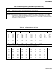
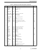
64 - - External pull-up -
65 BEEP Output Audio beep tone -
66 - - - -
67 - - - -
68 - - - -
69 - - - -
70 - - - -
71 P_HOLD - - -
72 FWE Input Flash memory Write Enable -
73 RESET Input Reset pulse input -
74 - - External pull-up -
75 L5V - - -
76 Vcc - L5V -
77 X-TAL Input System clock connection terminal -
78 EX-TAL Input System clock connection terminal -
79 Vss - Ground -
80 - - - -
81 Vcc - L5V -
82 TMUT - Not used -
83 T5C Output T5V supply control signal High
84 DPTT Output Delayed PTT signal Low
85 R5C Output R5V supply control signal High
86 - - - -
87 - - - -
88 NPSPAC Output Controls NPSPAC channel audio level High
89 MSO Output Serial data output -
90 MSI Input Serial data input -
91 SER_CLOCK Output Serial data clock -
92 - - - -
93 Avcc - L5V -
94 Vref - L5V -
95 BATT(VCC) Input Low battery voltage detection -
96 RSSI Input RSSI (Receive Signal Strength Indicator) -
97 L5V - L5V -
98 Ground - Ground -
99 - - External pull-up -
100 - - External pull-up -
101 - - External pull-up -
102 VVC_LVL - - -
103 AVss - Ground -
104 Vss - Ground -
105 TEST Output Bypass transmit data filter High
106 TXPREC Output Subaudible signaling tone/damp signal output -
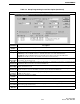
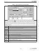
Table 4-1 Microprocessor U208 Pin Descriptions (Continued)
Pin No. Port Name In/Out Descriptions Active