
Service manual


CIRCUIT DESCRIPTION
4-6
November 2001
Part No. 001-7240-001
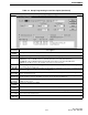
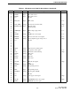
21 KEYR1 Input Key matrix scan in -
22 KEYR2 Input Key matrix scan in -
23 KEYR3 Input Key matrix scan in -
24 Vss - Ground -
25 - - - -
26 PTT_OUT Input PTT switch Low
27 - - - -
28 CLK_SHIFT Output Clock shift control (H = shift) High
29 KEYPAD_INT Input Keypad control Low
30 - - External pull-up -
31 - - - -
32 OFFREQIN Input Main voltage supply switch Low
33 Vcc - L5V -
34 DTMFT Output DTMF mute control signal Low
35 - - - -
36 RMUTE Output Receive audio mute control signal Low
37 AMUTE Output Audio amplifier supply voltage control High
38 Vss - Ground -
39 - - - -
40 - - - -
41 - - - -
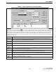
42 - - - -
43 DISST Output LCD driver chip enable signal -
44 PT Output Compander control signal Low
45 W_N Output Wide/narrow band switching High
46 PLLSK Output PLL clock -
47 Vss - Ground -
48 PLLSO Output PLL data -
49 PLLST Output PLL strobe -
50 - - - -
51 ULOCK Input PLL unlocked signal High
52 Vcc - L5V -
53 DTMFSO Output DTMF data -
54 TXD Output Programming data out -
55 - - - -
56 RXD Input Programming data in -
57 DTMFCK Output Clock signal for DTMF -
58 - - - -
59 Vss - Ground -
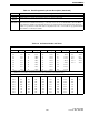
60 S5C Output +5C supply control signal High
61 - - - -
62 SN_TR Output SMARTNET circuit control signal High
63 FEPCS Output EEPROM chip select signal -
Table 4-1 Microprocessor U208 Pin Descriptions (Continued)
Pin No. Port Name In/Out Descriptions Active