
Datasheet


v1.0 / Modification rights reserved
8
EEH210
6.2. senDing a commanD
After sending the Start condition, the subsequent I
2
C header consists of the 7 bit I
2
C device address ‘1000000’ and an
SDA direction bit (Read R: ‘1’, Write W: ‘0’). The sensor indicates the proper reception of a byte by pulling the SDA pin
low (ACK bit) after the falling edge of the 8th SCL clock.
After the issue of a measurement command (‘11100011’ for temperature, ‘11100101’ for relative humidity), the MCU must
wait for the measurement to complete. The basic commands are summarized in Table 8.
COMMAND COMMENT CODE
Trigger T+RH measurement hold master 11100001
Trigger T measurement hold master 11100011
Trigger RH measurement hold master 11100101
Trigger T+RH measurement no hold master 11110001
Trigger T measurement no hold master 11110011
Trigger RH measurement no hold master 11110101
Write user register 11100110
Read user register 11100111
Soft reset 11111110
Table 10: Basic command set, RH stands for relative humidity, and T stands for temperature.
6.3. holD / no holD master moDe
There are two different operation modes to communicate with the sensor: Hold Master mode or No Hold Master mode.
In the first case the SCL line is blocked (controlled by sensor) during measurement process while in the latter case the
SCL line remains open for other communication while the sensor is processing the measurement.
No hold master mode allows for processing other I
2
C communication tasks on a bus while the sensor is measuring. A
communication sequence of the two modes is displayed in Figure 9 and Figure 10, respectively.
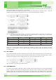
In the hold master mode, the EEH210 pulls down the SCL line while measuring to force the master into a wait state. By
releasing the SCL line the sensor indicates that internal processing is terminated and that transmission may be continued.
Figure 11: Hold master communication sequence – grey blocks are controlled by EEH210. Bit 45 may be changed to NACK followed by
Stop condition (P) to omit checksum transmission.
In no hold master mode, the MCU has to poll for the termination of the internal processing of the sensor. This is done by
sending a Start condition followed by the I
2
C header (10000001) as shown in Figure 10.
If the internal processing is finished, the sensor acknowledges the poll of the MCU and data can be read by the MCU. If
the measurement processing is not finished the sensor answers no ACK bit and the Start condition must be issued once
more.
For both modes, since the maximum resolution of a measurement is 14 bit, the two last least significant bits (LSBs, bits
43 and 44) are used for transmitting status information. Bit 1 of the two LSBs indicates the measurement type (‘0’:tem-
perature, ‘1’:humidity). Bit 0 is currently not assigned.