
Datasheet


7
EEH210
v1.0 / Modification rights reserved
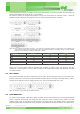
SEL[1:0] SCL/SPC SDA/SDIO DA CSB
00 I
2
C Hi-z Hi-z
01 0 PWM : T
Hi-z Hi-z
1 PWM : RH
10 0 PDM : T
1 PDM : RH
11 SPI OUT 0
Table 8: SEL[1:0] pin setting condition table
The SCL pin has to be fixed as ‘L’ or ‘H’ under PWM/PDM mode.
5.7. startuP sensor
As a first step, the sensor is powered up to the chosen supply voltage VDD (typical 3.0 V). After power-up, the sensor
needs at most 10 ms, while SCL is high, for reaching idle state, i.e. to be ready accepting commands from the master
(MCU) or the sensor starts measuring and providing data on PWM/PDM bit-stream.
Whenever the sensor is powered up, but not performing a measurement or communicating, it is automatically in idle state
(sleep mode).
5.8. Power on/oFF sequence
The recommended initial supply voltage (VDD) of EEH210 before power on state is Ground (VSS) level.
PARAMETER SYMBOL CONDITION MIN TYP MAX UNITS
Reset threshold voltage VL VDD=3V - - 0.2(TBD) V
Under threshold duration TL 0.5(TBD) - - sec
VCC rising slew rate VSL 0.25(TBD) - - V/ms
Table 9: Power On/Off Timing specifications. Entities are displayed in Figure 9
Figure 9: Power On/Off Sequence for proper operation.
6. communication by i
2
c Protocol with sensor
6.1. start / stoP sequence on i
2
c
I
2
C communication can be initiated by sending a START condition from the master, a high-to-low transition on the SDA
line while the SCL is high. A Stop condition, a low-to-high transition on the SDA line while the SCL input is high, is sent by
the master (see Figure 10).
Figure 10: Definition of I
2
C Start and Stop Conditions