
Datasheet


v1.0 / Modification rights reserved
6
EEH210
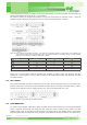
5.2. Pin DescriPtion
Table 7: Pin description table
NAME PIN# TYPE DESCRIPTION
NC 1 NC No connect
CSB 2 I / NC
SPI mode: chip select input
I
2
C,PWM, PDM mode: floating (NC)
DA 3 O / NC
SPI mode: Data available output signal
I
2
C, PWM, PDM mode: floating (NC)
VDD 4 P VDD Power Supply
NC 5 NC No connection
SDA / SDIO 6 I/O I
2
C / SPI serial data signal & PWM / PDM Output
SCL / SPC 7 I/O I
2
C / SPI serial clock signal
SEL0 8 I Mode Selection
SEL1 9 I Mode Selection
VSS 10 G Ground
EP Exposed Pad. EP is electrically connected to GND.
5.3. Power Pins (vDD, vss)
The recommended supply voltage of EEH210 is 3.0 V. Supply Voltage (VDD) and Ground (VSS) must be decoupled with
a 100 nF capacitor, placed as close as possible to the sensor..
5.4. i
2
c/sPi moDe selection, csb
To select the I
2
C interface, the SEL[1:0]=00 & CSB= floating (internal pull-down), to select the SPI interface, SEL[1:0]=11
& CSB=input
5.5. serial clock, scl/sPc
SCL is used to synchronize the communication between micro-controller (MCU) and the sensor. Since the interface con-
sists of fully static logic there is no minimum SCL frequency. SPC is the serial port clock and it is controlled by the SPI
master.
5.6. serial Data & bit stream, sDa/sDio
The SDA/SDIO port is used as two purposes according to the SEL[1:0] pin setting. The first is as I
2
C/SPI interface data
port and the second is usage as PWM/PDM output port.
On SDA/SDIO the sensor is providing PWM/PDM output. The signal is carrying humidity or temperature data depending
on SEL[1:0] setting. Refer to the Table 7.
When EEH210 is used at I
2
C interface mode, the SDA pin is used to transfer data in and out of the sensor. For sending a
command to the sensor, SDA is valid on the rising edge of SCL and must remain stable while SCL is high. After the falling
edge of SCL the SDA value may be changed. For safe communication SDA shall be valid tSU and tHD before the rising
and after the falling edge of SCL, respectively – see Figure 4. For reading data from the sensor, SDA is valid tVD after
SCL has gone low and remains valid until the next falling edge of SCL.
To avoid signal contention the micro-controller unit (MCU) must only drive SDA and SCL low. External pull-up resistors
(e.g.10kΩ),arerequiredtopullthesignalhigh.Forthechoiceofresistorsizepleasetakebuscapacityrequirementsinto
account (compare Table 5). It should be noted that pull-up resistors may be included in I/O circuits of MCUs. See Table 4
and Table 5 for detailed I/O characteristic of the sensor.
When EEH210 is used at SPI interface mode, the SDIO pin is the serial port data input and output.
This pin is driven at the falling edge of SPC and should be captured at the rising edge of SPC. – see Figure 6.