
Datasheet


3
EEH210
v1.0 / Modification rights reserved
Figure 4: Typical and maximal tolerance for temperature
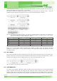
3.3. oPerating range
The standard working range with regard to the humidity / temperature limits is shown by the dark gray area in Figure 5.
The relative humidity signal may offset temporarily as a result of continuous exposure to conditions outside the dark gray
region, especially at humidity > 80 % RH. If the sensor is brought back to the standard working range, the initial values
will recover. Applications with high humidity at high temperatures will result in slower recovery. Reconditioning procedures
(see 8.5) can accelerate this process. Although the sensors would not fail beyond standard working range limits, the
specification is guaranteed within the standard working range only.
Figure 5: Working range
20
0
60
80
100
40
0 20 40 80 100 12060-20-40
Temperature [°C]
Relative Humidity [%]
standard
working
range
extended
working
range
4. electrical characteristics
4.1. absolute maximum ratings
The absolute maximum ratings as given in Table 3 are stress ratings only and give additional information. Functional
operation of the device at these conditions is not implied. Exposure to absolute maximum rating conditions for extended
periods may affect the device reliability (e.g. hot carrier degradation, oxide breakdown).
SYMBOL PARAMETER MIN MAX UNIT
VDD Power Supply -0.3 4.3 V
VLOGIC Digital I/O Pins (SDA, SCL, SEL[1:0] ) -0.3 VDD + 0.3 V
I
IN Input Current on any Pin -100 100 mA
T
STG Storage Temperature -55 150 °C
T
OP Operation Temperature -40 125 °C
Table 3: Absolute maximum ratings