
Datasheet


15
EEH210
v1.0 / Modification rights reserved
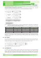
TEMP_OUT_H
Table 25: TEMP_OUT_H
15 14 13 12 11 10 9 8
TOUT15 TOUT14 TOUT13 TOUT12 TOUT11 TOUT10 TOUT9 TOUT8
Address: 2Bh (R)
Description: Temperature data
[7:0] TOUT15-TOUT8: Temperature data MSB
7.5. humiDity anD temPerature Data conversion
With the relative humidity data output DRH [= data of register address 29h, 28h] the relative humidity RH is obtained by the
following formula (result in %RH), no matter which resolution is chosen:
RH=-6+125∙
D
RH
2
16
The temperature T is calculated by inserting temperature data output DT [= data of register address 2B, 2A] into the fol-
lowing formula (result in °C), no matter which resolution is chosen:
T=-46.85+175.72∙
D
T
2
16
8. stanD-alone relative humiDity outPut
8.1. Pwm outPut
PWM signal runs on a base frequency of 120Hz, the data signal is provided on SDA line. By setting SEL[1:0] as ‘01’, the
PWM output mode is selected. SCL level setting ‘1’ for humidity and ‘0’ for temperature output mode is possible. The
sensor measures twice per second. Output resolution of RH and Temperature are set to 10bit and 12 bit each.
PWM Specification
Pulse Width Modulation runs on a constant frequency and the measured information is provided as duty cycle on that
frequency – see Figure 17.
Figure 17: PWM signal. Base frequency runs constantly at approximately 120 Hz. hence tF is about 8.3ms. The signal is provided on tPW
as a ratio of tF.
The measured data – either humidity or temperature – is provided as ratio of tPW and tF. tPW shall always be given as ratio
of t
F to make it independent of variations of the base frequency.
Conversion of Signal Output
The sensor reading is linear and hence it can be converted to a physical value by an easy linear equation.
With the relative humidity signal output the relative humidity RH is obtained by the following formula (result in %RH):
RH=-6+125∙
t
PW
tF