
Datasheet


13
EEH210
v1.0 / Modification rights reserved
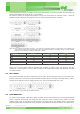
Address: 20h (R/W)
Description: [7] PD: power down control ( 0: power down mode, 1 : active mode)
[6:3] Reserved
[2] BDU: block data update
(0: continuous update, 1: output register not updated until MSB and LSB reading)
[1:0] ODR1, ODR0: output data rate selection
Table 18: CTRL_REG1
ODR1 ODR0 HUMIDITY (HZ) TEMPERATURE (HZ)
0 0 One shot
0 1 1 Hz 1 Hz
1 0 0.2 Hz 0.2 Hz
1 1 0.1 Hz 0.1 Hz
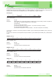
CTRL_REG2
Table 19: CTRL_REG2
7 6 5 4 3 2 1 0
BOOT Reserved ONE_SHOT
Address: 21h (R/W)
Description: Control register.
[7] BOOT: Reboot memory content (0: normal mode, 1: reboot memory content)
[6:1] Reserved
[0] One shot enable (0: waiting for start of conversion, 1: start for a new dataset)
The BOOT bit is used to refresh the content of the internal register stored in the eFUSE block. At device power-up, the
content of eFUSE memory block is transferred to the internal registers related to trimming functions to permit good behav-
ior of the device itself. If, for any reason, the content of the trimming registers is modified, it is sufficient to use this bit to
restore the correct values. When the BOOT bit is set to ‘1’ the content of the internal eFUSE is copied inside the corre-
sponding internal registers and is used to calibrate the device. These values are factory trimmed and are different for every
device. They permit good behavior of the device and normally they should not be changed. At the end of the boot process,
the BOOT bit is set again to ‘0’
The ONE_SHOT bit is used to start a new conversion. In this situation a single acquisition of temperature and humidity is
started when the ONE_SHOT bit is set to ‘1’. At the end of conversion the new data are available in the output register,
the STATUS_REG[0] and STATUS_REG[1] bits are set to ‘1’ and the ONE_SHOT bit comes back to ‘0’ by hardware.
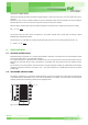
CTRL_REG3
Table 20: CTRL_REG3
7 6 5 4 3 2 1 0
DA_H_L PP_OD Reserved DA_EN Reserved
Address: 22h (R/W)
Description: Control register for data available output signal
[7] DA_H_L : Data available output signal active high, low
(0: active high –default, 1: active low)
[6] PP_OD: Push-pull / Open Drain selection on pin DA
(0: push-pull – default, 1: open drain)
[5:3] Reserved
[2] DA_EN: Data available enable
(0: Data available disabled – default, 1: Data available signal available on pin DA)
[1:0] Reserved