
Installation Manual

DynoRaxx Evolution PR Guide to Code Compliant Installation
4 | P a g e 8 6 6 . 6 2 0 . 2 4 1 0 | d y n o r a x x . c o m
II. Simplified Procedure for Calculating Design Wind Loads
Several methods exist to determine the design wind load on a particular fixed structure. For the purpose of
this manual, the methodology used as well as any relevant values and equations will be drawn from the ASCE
7-05 manual. Please refer to this manual if you have any questions about the procedure. In determining the
design wind load, we will make use of method 1, as discussed in ASCE 7-05 section 6.4.
In calculating the design wind loads, we assume that the solar modules are placed parallel to the racking
surface.
The application of method 1 is subject to the following restrictions:
1. The mean roof height h must be less than or equal to 60 ft ( )
2. The building must be enclosed. Method 1 does not allow for partially enclosed structures.
3. The building is regularly shaped; that is it does not have any unusual geometrical patterns in its spatial
form
4. The building is not placed at an extreme geographic location where the environment may greatly affect
wind load
5. The building has either a flat roof, a gable roof with a pitch less than 45 degrees or a hip roof with a
pitch of less than 27 degrees.
If the installation site does not conform to the restrictions above, please consult a professional engineer. For
further clarification, please refer to ASCE 7-05 for more information on method 1, as outlined in section 6.4.
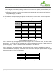
In order to determine the design wind load for components and cladding, the following equation will be
utilized:
(psf)
Where
= adjustment factor for building height and exposure classifications
Topographic factor evaluated at the mean roof height h
I = Importance factor
Simplified design wind pressure for Exposure B, at h=30 ft, I= 1.0
The reference used in this manual is:
ASCE/SEI 7-05, Minimum Design Loads for Buildings and Other Structures