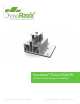
DynoRaxx® EVOLUTION PR Guide to Code Compliant Installation Publication Number 100611 866.620.2410 | dynoraxx.
DynoRaxx Evolution PR Guide to Code Compliant Installation Table of Contents I. Installer Responsibilities ................................................................................................... 3 II. Simplified Procedure for Calculating Design Wind Loads .................................................. 4 III. Calculating the Total Design Wind Load ........................................................................... 5 A. IV. Wind Design Load Worksheet ...........................
DynoRaxx Evolution PR Guide to Code Compliant Installation I. Installer Responsibilities: Thank you for choosing Evolution PR, a revolutionary technology for Pitched-Roof Racking for PV Mounting. Evolution PR pitched-roof solar racking system is designed and engineered for commercial and residential solar racking applications. The proprietary and patent-pending design allows the solar racking to be installed on all pitched roof systems for a long lasting product life and economical solution.
DynoRaxx Evolution PR Guide to Code Compliant Installation II. Simplified Procedure for Calculating Design Wind Loads Several methods exist to determine the design wind load on a particular fixed structure. For the purpose of this manual, the methodology used as well as any relevant values and equations will be drawn from the ASCE 7-05 manual. Please refer to this manual if you have any questions about the procedure.
DynoRaxx Evolution PR Guide to Code Compliant Installation III. Calculating the Total Design Wind Load A. Wind Design Load Worksheet: The following worksheet provided below will allow you to record the relevant values required in computing the total design wind load. Work through the tasks listed in the remainder of the section, and record the appropriate value in the given space.
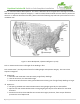
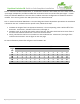
DynoRaxx Evolution PR Guide to Code Compliant Installation Task 1: Calculate the Basic Wind Speed V. This value is defined to be: the largest three second gust of wind at 33ft above the ground in exposure category C. It will be assumed that the wind will come from any horizontal direction. In order to determine this value, please consult the following map and look up the value of V in the installation site: Figure 1: Basic Wind Speed, V (ASCE 7-05 figure 6-1 p.
DynoRaxx Evolution PR Guide to Code Compliant Installation Exposure D: A building at the shoreline (excluding shorelines in hurricane-prone regions) with wind flowing over open water for a distance of at least 1 mile Shorelines in exposure D include inland waterways, the Great Lakes, and coastal areas of California, Oregon, Washington, and Alaska For further details on exposure categories, please consult 6.5.6.3 in the ASCE 7-05.
DynoRaxx Evolution PR Guide to Code Compliant Installation Occupancy Category Nature of Occupancy I Buildings and other structures that represent a low hazard to human life in the event of failure, including but not limited to: Agricultural Facilities Certain temporary facilities Minor storage facilities II III Buildings and other structures except those listed in Categories I, III, and IV IV Structures that represent a substantial hazard to human life in the event of failure including, but no
DynoRaxx Evolution PR Guide to Code Compliant Installation Task 6: Calculate the Effective Wind Area, A. As defined in section 6.2 of the ASCE, this area is taken to be the “span length multiplied by an effective width that need not be less than one-third the span length.” In other words, the Effective Wind Area is the area of the smallest continuous configuration of modules that will be installed. If this area is greater than 100 square feet, then 100 will be used. Task 7: Determine the Roof & Wall Zone.
DynoRaxx Evolution PR Guide to Code Compliant Installation Task 7: (Continued) In the figure shown below, identify the location of the installation site, and determine the angle of the roof. Then choose the appropriate zone as per the specifications. The zoning is determined as follows: Interior Zones are Zone 1/Walls are Zone 4 End Zones are Zone 2/Walls are Zone 5 Corner Zones are Zone 3 Taken from ASCE 7-05, figure 6-3 p. 41 10 | P a g e 866.620.2410 | dynoraxx.
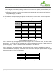
DynoRaxx Evolution PR Guide to Code Compliant Installation Task 8: Determine . From Tasks 6, 7 we have determined both the Effective Wind Area A, and the Roof/Wall Zoning. With this information in hand, look up the value of the Net Design Wind Pressure, , as specified in the tables shown below. The two sets of values underneath the Basic Wind Speed represent the down/uplift forces. The positive values are the down-forces, and corresponds to the force acting towards the surface.
DynoRaxx Evolution PR Guide to Code Compliant Installation From ASCE 7-05, figure 6-3 p. 42-43 12 | P a g e 866.620.2410 | dynoraxx.
DynoRaxx Evolution PR Guide to Code Compliant Installation IV. Calculating the Snow Load: A. Snow Loading Worksheet Included below is a worksheet of the values needed to compute the snow load.
DynoRaxx Evolution PR Guide to Code Compliant Installation B. Snow Loading Calculation Procedure This section is concerned with the effects of snow loading on a particular fixed structure. On sloped roofs, the snow load is: Where: represents the sloped roof snow load is the roof slope factor is the flat roof snow load Hence, in order to calculate the sloped roof snow load, one must find the corresponding flat roof snow load, and multiply that value with the appropriate coefficients.
DynoRaxx Evolution PR Guide to Code Compliant Installation Task 4: Determine the Importance Factor I. See page 7 for the structure classification descriptions. After selecting the appropriate category for the installation site, look up the corresponding value in the following table: Category I II III IV I 0.8 1.0 1.1 1.2 Taken from table 7-4, p. 93 of the ASCE 7-05 Task 5: From the values recorded from the previous steps, calculate the flat roof snow load, .
DynoRaxx Evolution PR Guide to Code Compliant Installation The next two pages include the values of the various ground snow loads in the United States. If your location is not included, please consult a local engineer. 16 | P a g e 866.620.2410 | dynoraxx.
DynoRaxx Evolution PR Guide to Code Compliant Installation 17 | P a g e 866.620.2410 | dynoraxx.
DynoRaxx Evolution PR Guide to Code Compliant Installation Task 6: Calculate the sloped roof snow load , using the formula from above: . The values of are determined based upon the thermal factor, and the state of the roof. After installing the solar panels upon the roof, the area in consideration becomes a “slippery surface.” As for such, when looking up values in the table shown below, please refer to the dashed lines. For more information, please refer to section 7.4 of the ASCE 7-05.
DynoRaxx Evolution PR Guide to Code Compliant Installation V. Load Combinations Often times, there is a good chance that various types of system loads are acting on a system simultaneously. Because these various loads provide different cumulative loads, the combination that produces the highest total system load must be taken into consideration. Hence, this value shall govern the system design. Shown below are the different cumulative loads as taken from Section 2.4 of the ASCE 7-05.
DynoRaxx Evolution PR Guide to Code Compliant Installation VI. Roof Mounting: The Evolution PR system is designed to be attached directly to the roof deck of the customer’s house. With the preliminary analysis of the systems loading completed, it is necessary to work out the details for the roof mounting, in order to insure a proper and secure installation of the racking system. The main concern of the roof mounting analysis is the withdrawal load.
DynoRaxx Evolution PR Guide to Code Compliant Installation VII. Calculation of Critical Test Load The purpose of this section is to go through the calculations described in the manual, by applying it to a critical test load. Here the critical test load signifies the highest stress loads a system may theoretically come to experience. As for such, we will make the following assumptions in our calculations: 1. 2. 3. 4. 5. 6. 7. 8.
DynoRaxx Evolution PR Guide to Code Compliant Installation VIII. Evolution PR Installation Instructions: Evolution PR is easily adaptable to a variety of site plans, allowing flexibility to work around mild obstacles and gives leeway to human error in array alignment. In order to insure as efficient installation as possible, installers should follow these guidelines as close as possible: Step 1: Start by using a chalk line to make a square for your solar array.
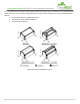
DynoRaxx Evolution PR Guide to Code Compliant Installation Step 3: After positioning the Evolution PR, take off the butyl mastic tape and secure its position onto the roof. Taking the TEK self-tapping screws, attach them to the roof through the designated holes. Step 1 Step 2 Step 4: Continuing down the chalk line, attach the next Evolution PR a few feet apart from the first, and secure it to the roof. Repeat this step all the way to the other corner. 23 | P a g e 866.620.2410 | dynoraxx.
DynoRaxx Evolution PR Guide to Code Compliant Installation Step 5: Position the first solar module so a ¼ of its length extends beyond the first two bottom bases. After positioning it, place it under the clamps of the Evolution PR. Step 6: Add a new row of Evolution PR bases, approximately in line with the first set. The Evolution PR has channels, allowing for flexibility in positioning. Attach the solar panel under the clamps of these new set of mounts. 24 | P a g e 866.620.2410 | dynoraxx.
DynoRaxx Evolution PR Guide to Code Compliant Installation Step 7: Secure the solar panel in place by screwing down the clamps on the base row. Step 8: Repeat steps 5-7 until first column has all modules placed. Make sure to screw down the clamps of the previous row, to properly secure module in place. 25 | P a g e 866.620.2410 | dynoraxx.
DynoRaxx Evolution PR Guide to Code Compliant Installation Step 9: When the end of the column has been reached, attach the last set of Evolution PR bases by positioning the deck screw holes under the last module. Attaching the butyl mastic tape to the roof, fasten the last row of Evolution PRs in position, and secure the solar panel under the clamps. Screw down any remaining clamps, insuring that the modules are properly installed.