
Installation Guide


SV-COM-760, SV-COM-T25 and SV-COM-T83 Installation and Configuration
SkyView System Installation Guide – Revision AK (draft) 16-9
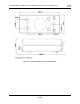
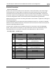
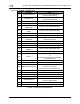
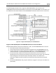
Transceiver Module – D25M Pinout
Pin
Function
Notes
1
PHONES GROUND
Connect to SV-INTERCOM-2S Pin 1
(Inside shielded cable)
2
PHONES OUT
Connect to SV-INTERCOM-2S Pin 14
(Inside shielded cable)
3
No connection
Do not connect
4
No connection
Do not connect
5
DATA RX from SV-
COM-PANEL
Connect to SV-COM-PANEL Pin 5
6
DATA TX to SV-COM-
PANEL
Connect to SV-COM-PANEL Pin 4
7
No connection
Do not connect
8
No connection
Do not connect
9
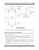
MICROPHONE / PTT
GROUND
Connect to SV-INTERCOM-2S Pin 1
See diagram below
10
GROUND
Do not connect
11
No connection
Do not connect
12
No connection
Do not connect
13
SV-COM-PANEL
ENABLE
Connect to SV-COM-PANEL Pin 6
14
No connection
Do not connect
15
PTT IN
Connect to SV-INTERCOM-2S Pin 12
or
Push Button Normally Open (PBNO)
to Ground (Pin 9)
16
No connection
Do not connect
17
No connection
Do not connect
18
TRANSMIT INTERLOCK
(Use only when there are two
transceiver modules.)
Connect to the other radio’s PTT.
19
GROUND IN
Connect to Ground Bus
20
No connection
Do not connect
21
No connection
Do not connect
22
GROUND IN
Connect to Ground Bus
23
MICROPHONE IN
Connect to SV-INTERCOM-2S Pin 25
(Inside shielded cable)
24
POWER IN
10-30V DC @ 5A
25
POWER IN
10-30V DC @ 5A
Table 96 – SV-COM-760/T25/T8 D25M Pinout