
Installation Guide


SV-COM-760, SV-COM-T25 and SV-COM-T83 Installation and Configuration
16-8 SkyView System Installation Guide – Revision AK
(draft)
Electrical Connections
Harness Construction
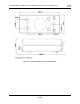
Because the transceiver module can be mounted in a variety of locations, the harness length
requirements will vary from airplane to airplane. Thus, Dynon Avionics does not supply pre-
manufactured harnesses between the transceiver module and SV-COM-PANEL. Instead, your
transceiver module and SV-COM-PANEL include connectors and pins to generate a wide variety
of harness configurations. Refer to the sections below for detailed wiring information.
Additional harness construction and wiring information can be found in Appendix C: Wiring and
Electrical Connections.
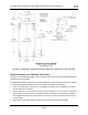
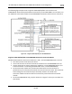
The SV-COM-PANEL has two (electrically identical) D9M connectors for connection to SkyView
Network and one D15M connector for connection with the transceiver module and an optional
Frequency Flip/Flop pushbutton input.
The transceiver modules have one D25M connector for connection to the SV-COM-PANEL,
power, audio, and Push to Talk (PTT). A single TNC Female connector (SV-COM-T25 and SV-
COM-T83) attaches to the antenna whereas the SV-COM-760 uses a BNC connector.
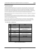
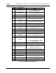
SV-COM-PANEL – D15M Pinout
Pin
Function
Notes
1
POWER IN
10-30V DC @ 5A
2
GROUND IN
Connect to Ground Bus
3
Ground Out
Optional - For Grounding Pin 7
(Flip/Flop Switch). Switch may also be
grounded locally.
4
Panel RX / Transceiver TX
Connect to Transceiver Module Pin 6
5
Panel TX / Transceiver RX
Connect to Transceiver Module Pin 5
6
Enable
Connect to Transceiver Module Pin 13
7
External Flip/Flop
(optional)
Push Button Normally Open to Ground
(Pin 3 or local ground)
8
No Connection
(Pin not used)
9
No Connection
(Pin not used)
10
No Connection
(Pin not used)
11
No Connection
(Pin not used)
12
No Connection
(Pin not used)
13
No Connection
(Pin not used)
14
No Connection
(Pin not used)
15
No Connection
(Pin not used)
Table 95 – SV-COM-PANEL D15M Pinout