
Installation Guide


SV-COM-760, SV-COM-T25 and SV-COM-T83 Installation and Configuration
SkyView System Installation Guide – Revision AK (draft) 16-3
Physical Installation
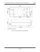
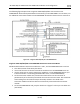
SV-COM-PANEL – VERTICAL Installation Dimension Quick Overview
• Panel Cutout: (irregular – see drawing)
• Bezel Outline: 1.80” W x 3.532” T (45.72 mm W x 89.71 mm T)
• Note that the SV-COM-PANEL/V is sized such that two units can be stacked to
the same height as the height of an SV-D1000 display.
SV-COM-PANEL - HORIZONTAL Installation Dimension Quick Overview
• Panel Cutout: (irregular – see drawing)
• Bezel Outline: 3.532” W x 1.80” T (89.71 mm W x 45.72 mm T)
To mount an SV-COM-PANEL, cut the opening in your panel, drill out the mounting holes, install
nutplates, and use the included mounting screws to fasten the display to the panel.
The SV-COM-X25/X83 is shipped with #6-32 hex-drive round head fasteners. Fasteners are 5/8”
long and require a 5/64” hex drive tool. Dynon Avionics recommends fastening the included
mounting screws to nut plates installed behind the panel. If access behind the panel allows,
standard #6-32 lock nuts or nuts with lock washers can be used. Do not rivet the SV-COM-
PANEL to the panel as this will hinder future removal if necessary.
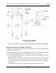
Mounting Dimensions
The following diagrams are NOT to scale. However, paper templates are included
with your SV-COM-X25/X83 and may also be downloaded from dynon.com/docs.