
Installation Guide


SV-COM-760, SV-COM-T25 and SV-COM-T83 Installation and Configuration
SkyView System Installation Guide – Revision AK (draft) 16-17
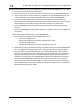
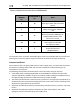
Phones / Headset Connections for SV-INTERCOM-2S
TRANSCEIVER
MODULE
Pin
SV-INTERCOM-2S
Pin
Notes
2
14
PHONES OUT
Audio signal from radio to headset
phones
1
1
PHONES GROUND
Shield connection for PHONES
OUT
15
12
PUSH TO TALK IN
When connected to GROUND, SV-
COM-X25/X83 switches from
Receive to Transmit
23
25
MICROPHONE IN
Audio signal from headset
microphone to radio
9
1
MICROPHONE / PTT GROUND
Shield connection for
MICROPHONE IN
Table 98 – Phones / Headset Connections for SV-INTERCOM-2S
To avoid noise, hum, and other undesirable signals, always use shielded cable for any low-level
audio signals such as microphone inputs and connect the shield of the cable as directed.
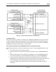
Antenna Installation
Dynon Avionics does not supply COM antennas, radio coaxial cable, or antenna TNC connectors.
The antenna (including coaxial cable and connector) should be installed according to the
manufacturer’s instructions.
The following considerations should be taken into account when siting the antenna:
• If two COM radios (including SV-COM-X25 or SV-COM-X83) are installed, the two COM
antennas should be installed as far apart as practical, ideally installing one COM antenna on
the upper fuselage and the other COM antenna on the lower fuselage.
• The antenna should be well removed from any projections, the engine(s) and propeller(s). It
should also be well removed from landing gear doors, access doors or other openings which
will break the ground plane for the antenna.
• Separation of COM antenna(s) from transponder(s) and GPS receivers / antennas: 2 feet (24
inches).
• Separation of COM antenna(s) from Automatic Direction Finder (ADF) or 121.5 MHz
Emergency Locator Transmitter (ELT): 4 feet (48 inches)