
Installation Guide


SV-COM-760, SV-COM-T25 and SV-COM-T83 Installation and Configuration
SkyView System Installation Guide – Revision AK (draft) 16-15
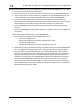
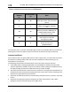
Figure 214 – Headset Jack Schematic Interpretation
Power/Ground Input
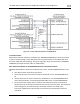
The TRANSCEIVER MODULE and SV-COM-PANEL require 10-30V DC. 20 AWG wire is
recommended for power and ground wires for the TRANSCEIVER MODULE. For all other
connections, 22 AWG wire is recommended.
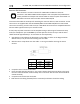
TRANSCEIVER
MODULE
Pin
SV-COM-PANEL
Pin
Notes
13
6
ENABLE
TRANSCEIVER MODULE -> SV-COM-
PANEL
5
5
DATA OUT
SV-COM-PANEL -> TRANSCEIVER
MODULE)
6
4
DATA IN
TRANSCEIVER MODULE -> SV-COM-
PANEL
Table 97 – SV-COM-PANEL to TRANSCEIVER MODULE Interconnections
Optional Flip / Flop Button
Pin 7 of the SV-COM-PANEL can be connected to a Push Button Normally Open (PBNO) and
GROUND. Pushing this button “flip flops” the ACTIVE and STANDBY frequency selection - the
same function as pressing in the TUNE knob on the SV-COM-PANEL. Typically, this signal is used
with a button on the stick.