
Installation Guide


SV-COM-760, SV-COM-T25 and SV-COM-T83 Installation and Configuration
16-14 SkyView System Installation Guide – Revision AK
(draft)
transceiver module #2 end of this cable is not electrically connected at transceiver
module #2.
• On the SV-INTERCOM-2S end, prep the shield into a "pigtail" so that you can solder to it
(see instructions below - Terminating Shielded Cables to Pin 1 of SV-INTERCOM-2S).
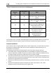
Terminating Shielded Cables to Pin 1 of SV-INTERCOM-2S
• Eight connections terminate into SV-INTERCOM-2S Pin 1:
o TRANSCEIVER MODULE #1 Pin 1
o Shield of the cable from TRANSCEIVER MODULE #1 Pins 1 and 2
o TRANSCEIVER MODULE #1 Pin 9
o Shield of the cable from TRANSCEIVER MODULE #1 Pins 23 and 9
o TRANSCEIVER MODULE #2 Pin 1
o Shield of the cable from TRANSCEIVER MODULE #2 Pins 1 and 2
o TRANSCEIVER MODULE #2 Pin 9
o Shield of the cable from TRANSCEIVER MODULE #2 Pins 23 and 9
Rather than trying to terminate these eight connections directly to SV-INTERCOM-2S Pin 1, we
suggest connecting a wire to Pin 1, then bond all nine connections together. One method is to
tie-wrap the bundle of wires and shields together, twist the wires together, and solder the nine
wires and shields. After the solder cools, use heat shrink tubing to insulate the connection. The
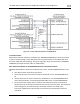
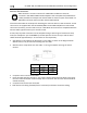
following figure depicts connecting a TRANSCEIVER MODULE directly to a single headset
(headphone + microphone) and a Push-To-Talk Switch when no intercom is used in a single-
place aircraft.
Figure 213 – TRANSCEIVER MODULE to Headset