
Installation Guide


SV-COM-760, SV-COM-T25 and SV-COM-T83 Installation and Configuration
16-10 SkyView System Installation Guide – Revision AK
(draft)
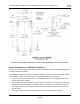
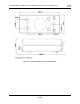
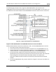
The following figure depicts how a single SV-COM-760/T25/T8 is connected to an SV-
INTERCOM-2S. Note that SkyView Network connection(s) on SV-COM-PANEL are not shown, nor
are additional connections between the SV-INTERCOM-2S and other devices that it connects to.
Figure 211 – Single SV-COM-760/T25/T8 to SV-INTERCOM-2S
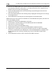
Single SV-COM-760/X25/X83 to SV-INTERCOM-2S Harness Construction Notes
Shielded cable between transceiver module Pins 2 and 1, and SV-INTERCOM-2S Pins 1 and 14:
• This cable consists of two wires plus shield.
• Use one of the wires to connect transceiver module Pin 2 to SV-INTERCOM-2S Pin 14.
• Use the other wire to connect transceiver module Pin 1 to SV-INTERCOM-2S Pin 1 (see
instructions below - Terminating Shielded Cables to Pin 1 of SV-INTERCOM-2S).
• On the transceiver module end, continue the shield as far into the connector as
possible until you're forced to pare it back to access the two inner wires. Put some heat
shrink tubing over the shield to keep it electrically isolated - the shield at the
transceiver module end of this cable is not electrically connected at the transceiver
module.
• On the SV-INTERCOM-2S end, prep the shield into a "pigtail" so that you can solder to it
(see below).