SV-INTERCOM-2S Installation and User’s Guide This product is not approved for installation in type certificated aircraft Document 102061-000, Revision A June, 2013 Copyright © 2013 by Dynon Avionics, Inc.
Contact Information Dynon Avionics, Inc. st 19825 141 Place NE Woodinville, WA 98072 Phone: (425) 402-0433 - 8:00 AM – 5:00 PM (Pacific Time) Monday – Friday Dynon Technical Support available 7:00 AM–4:00 PM (Pacific Time) Monday – Friday Email: support@dynonavionics.com Fax: (425) 984-1751 Dynon Avionics offers online sales, extensive support, and frequently updated information on its products via its Internet sites: www.dynonavionics.
Dynon Avionics retains the exclusive right to repair or replace the instrument or firmware or offer a full refund of the purchase price at its sole discretion. SUCH REMEDY SHALL BE YOUR SOLE AND EXCLUSIVE REMEDY FOR ANY BREACH OF WARRANTY. These instruments are not intended for use in type certificated aircraft at this time. Dynon Avionics makes no claim as to the suitability of its products in connection with FAR 91.205. Dynon Avionics’ products incorporate a variety of precise, sensitive electronics.
Table of Contents Contact Information ..................................................................................................................................................... iii Copyright ...................................................................................................................................................................... iii Limited Warranty ..........................................................................................................................
1. Introduction Thank you for purchasing the Dynon Avionics SV-INTERCOM-2S. This chapter provides some important cautionary information and general usage instructions for this guide. The printed version of this guide is in grayscale. Some figures and diagrams contain important color information. Reference the electronic version of this guide to view it in color. Before You Fly We strongly recommended that you read this entire guide before attempting to use the SVINTERCOM-2S in an actual flying situation.
Introduction wiki.dynonavionics.com–Dynon’s Documentation Wiki provides enhanced, extended, frequently updated online documentation contributed by Dynon employees and customers. forum.dynonavionics.com–Dynon’s Online Customer Forum is a resource for Dynon Avionics customers to discuss installation and operational issues relating to Dynon Avionics products. The Forum is especially useful for pilots with uncommon aircraft or unusual installation issues.
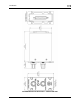
2. Installation While the SV-INTERCOM-2S is designed to seamlessly complement a SkyView System, its design is flexible enough to be used in any experimental or light sport aircraft panel that does not required a TSO’d intercom. For a neat panel installation, a vertically-mounted SV-INTERCOM-2S is dimensioned to 50% of the height of a SkyView SV-D1000 display’s bezel.
Installation SV-INTERCOM-2S Unit Dimensions – NOT ACTUAL SIZE 2-2 SV-INTERCOM-2S Installation and User Guide - Revision A
Installation Electrical Installation * == While the audio grounds labeled with a * ultimately come back to the main ground on pin 1, they should NOT be wired directly from the source audio device to any ground (pin 1 or otherwise) directly. Instead, to minimize noise and interference, their ground lines should be routed with their audio signal inside the required shielded cable as far as possible and connected to ground as close to the intercom as possible.
Installation * == While the audio grounds labeled with a * ultimately come back to the main ground on pin 1, they should NOT be wired directly from the source audio device to any ground (pin 1 or otherwise) directly. Instead, to minimize noise and interference, their ground lines should be routed with their audio signal inside the required shielded cable as far as possible and connected to ground as close to the intercom as possible.
Installation shield (which is also grounded at pin 1) at the intercom end of the harness is a suitable way to accomplish this goal. SV-INTERCOM2S Pin SkyView Unit Pin SV-INTERCOM-2S Function 1 N/A Master Ground In / Master Shield Ground. The shields of all shielded audio cables should be connected to this pin.
Installation SV-INTERCOM2S Pin SkyView Unit Pin SV-INTERCOM-2S Function Notes 14 SV-COM-425 #1 Pin 10 Radio 1 Headphones Input Connects to SV-COM-425 #1 / Radio #1 Headphones Output 15 SV-COM-425 #2 Pin 1 Radio 2 Microphone Output 16 N/A Copilot Push-To-Talk Switch 17 N/A Non-Muting Mono Aux Input This audio signal does not mute when audio signals are received on other inputs. Use this input for critical audio signals such as a NAV radio or avionics alerts.
Installation Using Dim Input (Pin 5) Without SkyView Displays Using Dim Input (Pin 5) Without SkyView If you are using the SV-INTERCOM-2S without a SkyView system, and want to vary the brightness of the SV-INTERCOM-2S’ backlighting, you must dim this using a PWM dimmer that switches the ground side of the lighting circuit. A varying voltage or resistance will not work. Hook pin 5 to the negative terminal of your dimmer and the transmit/power LED will dim with your dim control.
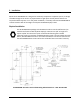
Installation a single point, with that point connected directly to Pin 1 (Master Ground) of the SV-INTERCOM-2S. Additionally, the point should be as close to the SV-INTERCOM2S side of your harness as possible. Dual Radio PTT Installation The SV-INTERCOM-2S has two separate radio outputs that can each be connected to an individual COM radio. The PTT output, therefore, needs to be externally switched so that you can control which radio receives the PTT signal (and therefore transmits).
Installation Figure 3 - Headset Jack Schematic Symbol Guide SV-INTERCOM-2S Installation and User Guide - Revision A 2-9
3. Using the SV-INTERCOM-2S The SV-INTERCOM-2S is a 2-Place Stereo Intercom for Sport Aircraft. It includes features: Ample inputs for EFIS systems, stereo music, and all the other technology in your panel. High-Fidelity Audio Circuitry: No more scratchy, garbled voices. Stereo music that sounds fantastic! Dual Radio Support: The SV-INTERCOM-2S has dual radio outputs for the well-equipped panel. Fail-safe between the pilot headset and primary radio that allows communication without intercom power.
Using the SV-INTERCOM-2S LED Power/Transmit Indicator The LED indicator light in the center of the Intercom is green when the Intercom is powered on. When either the pilot or co-pilot PTT switch is depressed, the LED becomes orange to indicate radio transmission. The LED can be dimmed by a capable device such as a Dynon SkyView system. There is no manual dimming control on the SV-INTERCOM-2S itself.
Using the SV-INTERCOM-2S Muting Inputs Whenever a radio or other non-muting input has audio activity, music and muting input volume is immediately decreased to near fully-muted so that you may hear important radio transmissions or audio alerts. When audio from radios/non-muting inputs ceases for a moment (.5 second), volume levels are automatically restored gradually over the next second.
4. Specifications SV-INTERCOM-2S Specifications Power Usage 0.1A at 14V Input Voltage 10-30V DC Weight Temperature Dimensions Radio Outputs Headsets Non-muting Inputs Muting Inputs 7.2 oz (204g) -40°C to +70°C 3.5” (89.71mm) x 1.80” (45.72mm) x 4.18” (106.17mm) (2) COM radio outputs. External PTT selector required. (2) stereo headsets supported. (1) stereo, differential, noise-rejecting EFIS input. (3) mono inputs for radios and other avionics. Primary radio fail-safe to pilot headset.