
Installation Guide User Manual

Autopilot Servo Installation, Configuration, and Calibration
10-10 SkyView System Installation Guide - Revision S
Autopilot System Electrical Installation
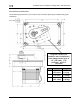
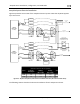
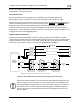
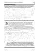
Figure 64 provides an overview of the autopilot electrical system. Note that SkyView supports
up to two servos.
Female DB9
Male DB9
YELLOW
GREEN
BLUE
WHITE/BLUE
SERVO
(SV32, SV42,
or SV52)
1
5
6
9
Female DB9
CONNECT
1
5 5
6
9 9
WHITE/BLUE
WHITE/GREEN
BLUE
GREEN
1
6
To SkyView
Network
SPLICE
SPLICE
SPLICE
RED
BLACK
BLACK - 20 AWG - To Aircraft Ground
WHITE/GREEN
Female DB9
Male DB9
YELLOW
GREEN
BLUE
WHITE/BLUE
SERVO
(SV32, SV42,
or SV52)
1
5
6
9
Female DB9
CONNECT
1
5 5
6
9 9
WHITE/BLUE
WHITE/GREEN
BLUE
GREEN
1
6
To SkyView
Network
SPLICE
SPLICE
SPLICE
RED
BLACK
BLACK - 20 AWG - To Aircraft Ground
WHITE/GREEN
Pilot-accessible
Disengage/CWS button
(Normally open, momentary)
Usually mounted to the stick
5 kohm
Optional resistor for
broken disengage
detection
Twisted Pair
8-10 twists/foot
Twisted Pair
8-10 twists/foot
YELLOW - To Disengage/CWS Button
YELLOW - To Disengage/CWS Button
(halve the current for 24 volt systems)
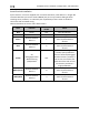
Servo
Powered,
disengaged
Engaged,
holding,
100% torque
Engaged,
moving,
100% torque
Unit
SV32 0.10 0.80 1.33 amps
SV42 0.10 1.11 2.03 amps
SV52 0.10 1.52 2.80 amps
- SERVO CURRENT DRAW AT 12 VOLTS -
Pilot accessible
servo power
switch/breaker
RED - 20 AWG - To Servo Power Switch/Breaker
RED - 20 AWG - To Servo Power Switch/Breaker
To Aircraft
Power
(10 to 30 volts)
Figure 64 – SkyView Autopilot System Electrical Installation Overview (All Connectors Rear View)
The following sections describe the electrical installation of each subsystem in detail.