
Installation Guide User Manual


Autopilot Servo Installation, Configuration, and Calibration
10-4 SkyView System Installation Guide - Revision S
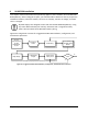
and associated linkage to move freely through the entire range of travel. To prevent the
possibility of the servo arm going OVER CENTER, the servo arm must not travel more than a
total of +/-60° from neutral position. When the aircraft controls are centered, the arm of the
servo should be perpendicular to the attaching push rod. If this is not the case, we recommend
adjusting the length of the push rod or consider a different mounting point. For maximum
efficiency and the lightest drag on the flight controls, you should choose the smallest servo that
provides sufficient torque to move and hold the flight controls with a minimum of slippage. A
diagram of servo torque versus mount position is shown on page 10-6.
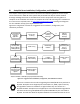
The servo arm must not rotate even near to the point called OVER CENTER, the
point at which the primary aircraft control would “lock up”. Over center happens
when the angle between the servo arm and the attached push rod becomes so
great that the control system cannot drive against the servo arm. To protect
against this possibility, a Range of Motion Limiting Bracket is supplied with each
Dynon Avionics servo. These brackets are drilled so that they can be mounted at
different angles as required (18° intervals). The brackets are supplied for the
protection of the pilot, and we recommend that the Range of Motion Limiting
Bracket be installed to ensure that an OVER CENTER condition cannot occur.
During normal servo operation, the Range of Motion Limiting Bracket should never
be used. It is only intended for use as a safety mechanism in the SkyView Autopilot
system. When installing the Range of Motion Limiting Bracket, only use the
supplied screws. Using longer screws to install the bracket, you will penetrate and
damage the electronics.
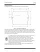
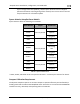
Once a suitable mounting point for each servo has been determined, the next step is to
fabricate a mount for the servo to attach to the aircraft. Generally this will be a bracket made of
sheet metal or corner stock. Dynon recommends using 6061 T6 aluminum with a minimum
thickness of 0.050” for the best balance of strength to weight. When fabricating a mounting
bracket, refer to the servo dimensions below. Be sure to leave ample room for the arm and
attached linkage to move through a complete range of motion without interference.
In normal operation, autopilot servos can reach temperatures that can be very
uncomfortable to, and perhaps cause burns to unprotected skin. Thus, servos
should be mounted in an area, or in such a manner to prevent accidental skin
contact. If mounting the servo in an exposed area is necessary, a shroud should be
installed (that doesn’t restrict ventilation) that protects against accidental skin
contact with the servos.