
Installation Guide User Manual

SV-EMS-220/221 Installation and Configuration
SkyView System Installation Guide – Revision S 7-69
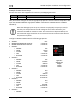
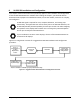
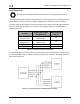
Example Contact Sensor Setup
Assume this sensor was mapped on the Sensor Input Mapping Wizard as:
PIN #
FUNCTION
SENSOR
NAME
C37 P9
CANOPY
Contact
CANOPY
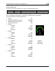
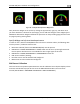
Now, we want to configure its alert and graphical properties. Go to the Sensor Setup Menu and
open the CANOPY CONTACT Page (SETUP MENU > EMS SETUP > SENSOR SETUP > CANOPY
CONTACT).
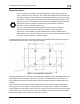
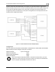
Note that although inputs set up as contacts can physically accept up to 15V (so
that they can accept nominal aircraft voltage as one of their two states), the
maximum the EMS can measure is 5.0V. This means that as depicted below, the
two measured ranges should be set to 0-2.5V and 2.5-5V to measure the absence
and presence of power.
Configure CANOPY CONTACT with the following properties:
ALARM: OFF
MAXIMUM GRAPHICAL DISPLAY: 5.0 VOLTS
MINIMUM GRAPHICAL DISPLAY: 0.0 VOLTS
RANGE 1
o ENABLE YES
o NAME OPEN
o COLOR RED
o TOP 5.0 VOLTS
o BOTTOM 2.5 VOLTS
RANGE 2
o ENABLE YES
o NAME CLOSED
o COLOR GREEN
o TOP 2.5 VOLTS
o BOTTOM 0.0 VOLTS
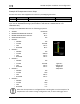
RANGE 3
o ENABLE NO
o NAME R3
o COLOR GREEN
o TOP 20.0 VOLTS
o BOTTOM 10.0 VOLTS
RANGE 4
o ENABLE NO
o NAME R4
o COLOR YELLOW
o TOP 10.0 VOLTS
o BOTTOM 5.0 VOLTS
RANGE 5
o ENABLE NO
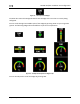
Figure 48 –
Anatomy of a
Widget:
Canopy
Contact