
Installation Guide User Manual


SV-EMS-220/221 Installation and Configuration
SkyView System Installation Guide – Revision S 7-51
Capacitance-to-Voltage Converter installation instructions.
Note that SkyView displays are typically preconfigured to use resistive probes. Using capacitive
sensors instead of resistive probes requires that you change EMS settings in a few places. First,
change the pins used for fuel quantity via the SETUP MENU > EMS SETUP > PIN SENSOR INPUT
MAPPING… menu. Then, delete the default fuel quantity widgets from each screen layout
under SETUP MENU > EMS SETUP > SCREEN LAYOUT EDITOR. Finally, add the new fuel quantity
widget(s) that will be available for the capacitive probes.
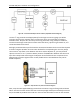
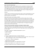
Ammeter Shunt
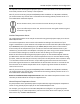
The ammeter shunt should be mounted so that the
metal part of the shunt cannot touch any part of the
aircraft. The ammeter shunt can be installed in your
electrical system in one of three locations as shown in
Figure 43.
If you have a Vertical Power VP-X system in your
aircraft, use either position A or position B. Position C is not useful in a VP-X installation
because the VP-X measures aircraft loads directly.
Position A–Ammeter indicates current flow into
or out of
your battery. In this position, it will show both positive and
negative currents (i.e., -60 amps to +60 amps).
Position B–Ammeter indicates only the positive currents
flowing from the alternator to both the battery and aircraft loads.
(0A-60A)
Position C–Ammeter indicates the current flowing only into the aircraft loads. (0A-60A)
Note that the ammeter shunt is not designed for the high current required by the
starter and must not be installed in the electrical path between the battery and
starter.
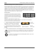
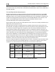
The Ammeter Shunt packaging may be marked 40mV/40A. However, Dynon rates
the shunt for up to 60A loads.
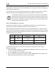
Pin
Color
Function
24
Orange/green
amps high
25
Orange/Violet
amps low
Table 42 – AMPS SHUNT Pins
Figure 42 – Amps Shunt