Autopilot Servo Installation Guide Generic (Push-Pull) This product is not approved for installation in type certificated aircraft Document 101046-000, Revision F January, 2013 Copyright © 2009-2013 by Dynon Avionics, Inc.
DYNON AVIONICS Contact Information Dynon Avionics, Inc. 19825 141st Place NE Woodinville, WA 98072 Phone: (425) 402-0433 - 8:00 AM – 5:00 PM (Pacific Time) Monday – Friday Dynon Technical Support available 7:00 AM–4:00 PM (Pacific Time) Monday – Friday Email: support@dynonavionics.com Fax: (425) 984-1751 Dynon Avionics offers online sales, extensive support, and frequently updated information on its products via its Internet sites: www.dynonavionics.com –Dynon Avionics primary web site; including: docs.
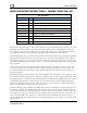
DYNON AVIONICS SERVO MOUNTING INSTRUCTIONS – GENERIC PUSH-PULL KIT Kit Contents Dynon Part # QTY Part Description 100836-000 2 Large Male Rod End 100982-006 1 Aluminum Tube - 8" (untapped) 100975-002 2 AN315-4R Jam Nut 100976-011 1 AN365-1032A Nylon Insert Lock Nut 100977-000 2 AN970-3 Large Flat Washer 100978-003 2 AN960-10 Small Flat Washer 100979-002 4 MS35333-39 #10 Internal Star Washer 100981-000 4 AN3H-3A Bolt - 3/8" 100981-005 1 AN3H-10A Bolt - 1" The generic servo push-pu
DYNON AVIONICS When cutting the push-pull rod to size, take into account the extra length provided by the unthreaded portion of each rod end. The distance between the servo arm and the control system attachment point must allow for the angle between the servo arm and the push rod to be at approximately 90º when the controls are at neutral. With the measurements taken, cut the tube down to the correct length and tap both ends to a depth of 1" using a plug type tap.
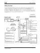
DYNON AVIONICS Wiring Overview The following diagram provides an overview of the autopilot-specific wiring installation. For the complete set of wiring and configuration instructions, please see the latest Installation Guide for your Dynon EFIS product. For a SkyView system please reference the Autopilot Servo Installation, Configuration, and Calibration chapter of your SkyView System Installation guide.
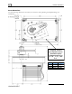
DYNON AVIONICS Servo Dimensions Use the following dimensions (in inches) for reference when planning and implementing your installation. Long-arm variants (not needed in most installations)have linkage mount holes at 1.5”, 1.75”, and 2.0” L Weight SV32 2.17” 2 lb SV42 3.10” 3 lb SV52 4.
DYNON AVIONICS Linkage mount position force and travel The two diagrams below illustrate the maximum travel and force available at each linkage mounting point. As can be seen, the closer you mount the linkage to the shaft, the more force the servo can deliver. However, this also means the travel of the arm is shorter. Again, ensure that the servo arm is nowhere near going over-center throughout the entire range of the control system. Standard Arm Max Linear Travel A: 2.6”, B: 2.2”, C: 1.
DYNON AVIONICS The autopilot safety shear screw should NEVER be removed or adjusted during this operation. If the shear screw has broken and needs replacement, there is specific documentation available for this purpose at http://docs.dynonavionics.com.