Autopilot Servo Installation Guide RV10 Pitch This product is not approved for installation in type certificated aircraft Document 101046-006, Revision F January, 2013 Copyright © 2009-2013 by Dynon Avionics, Inc.
DYNON AVIONICS Contact Information Dynon Avionics, Inc. 19825 141st Place NE Woodinville, WA 98072 Phone: (425) 402-0433 - 8:00 AM – 5:00 PM (Pacific Time) Monday – Friday Dynon Technical Support available 7:00 AM–4:00 PM (Pacific Time) Monday – Friday Email: support@dynonavionics.com Fax: (425) 984-1751 Dynon Avionics offers online sales, extensive support, and frequently updated information on its products via its Internet sites: www.dynonavionics.com –Dynon Avionics primary web site; including: docs.
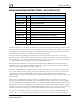
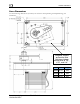
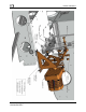
DYNON AVIONICS SERVO MOUNTING INSTRUCTIONS – RV-10 PITCH KIT Kit Contents Dynon Part # QTY Part Description 100836-000 2 Large Male Rod End 100966-008 1 Aluminum Pushrod Tube – 3.
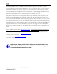
DYNON AVIONICS should be installed as close to the Dynon recommendation as possible, as changes will affect geometry. Dynon suggests installing the linkage at the outer-most hole of the servo arm. Changing this location will affect servo torque output, servo arm travel, control surface resolution, and the amount of force required to shear the safety screw, and should only be changed if the installer has an understanding of these implications.
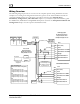
DYNON AVIONICS Wiring Overview The following diagram provides an overview of the autopilot-specific wiring installation. For the complete set of wiring and configuration instructions, please see the latest Installation Guide for your Dynon EFIS product. For a SkyView system please reference the Autopilot Servo Installation, Configuration, and Calibration chapter of your SkyView System Installation guide.
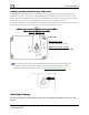
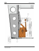
DYNON AVIONICS Servo Dimensions Use the following dimensions (in inches) for reference when planning and implementing your installation. Long-arm variants (as used for RV-6 Roll) have linkage mount holes at 1.5”, 1.75”, and 2.0” L Servo Mounting Instructions – RV-10 Pitch Kit 101046-006 Rev F Weight SV32 2.17” 2 lb SV42 3.10” 3 lb SV52 4.
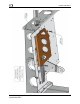
DYNON AVIONICS Linkage mount position force and travel The diagram below illustrates the maximum travel and force available at each linkage mounting point. As can be seen, the closer you mount the linkage to the shaft, the more force the servo can deliver. However, this also means the travel of the arm is shorter. Again, ensure that the servo arm is nowhere near going over-center throughout the entire range of the control system. Position A should be used in most RV-6 roll installations.
DYNON AVIONICS Servo Mounting Instructions – RV-10 Pitch Kit 101046-006 Rev F 7
DYNON AVIONICS Servo Mounting Instructions – RV-10 Pitch Kit 101046-006 Rev F 8
DYNON AVIONICS Servo Mounting Instructions – RV-10 Pitch Kit 101046-006 Rev F 9