AOA/Pitot Probe P/N 100141-000 Heated AOA/Pitot Probe P/N 100667-000 Installation Guide This product is not TSO’d and cannot be installed into traditional FAA Part 23 and similarly type-certificated aircraft Document 100740-001, Revision C October, 2014 Copyright © 2007-2014 by Dynon Avionics, Inc. Permission to print this manual is granted to third parties.
Contact Information Dynon Avionics, Inc. st 19825 141 Place NE Woodinville, WA 98072 Phone: (425) 402-0433 - 8:00 AM – 5:00 PM (Pacific Time) Monday – Friday Dynon Avionics Technical Support available 7:00 AM–4:00 PM (Pacific Time) Monday – Friday Email: support@dynonavionics.com Fax: (425) 984-1751 Dynon Avionics offers online sales, extensive support, and frequently updated information on its products via its Internet sites: www.dynonavionics.com –Dynon Avionics primary web site; including: http://docs.
IN NO EVENT SHALL DYNON AVIONICS BE LIABLE FOR ANY INCIDENTAL, SPECIAL, INDIRECT OR CONSEQUENTIAL DAMAGES, WHETHER RESULTING FROM THE USE, MISUSE OR INABILITY TO USE THIS PRODUCT OR FROM DEFECTS IN THE PRODUCT. SOME STATES AND COUNTRIES DO NOT ALLOW THE EXCLUSION OF INCIDENTAL OR CONSEQUENTIAL DAMAGES, SO THE ABOVE LIMITATIONS MAY NOT APPLY TO YOU. Dynon Avionics retains the exclusive right to repair or replace the instrument or firmware or offer a full refund of the purchase price at its sole discretion.
Table of Contents Contact Information .....................................................................................................................................................iii Copyright ......................................................................................................................................................................iii Limited Warranty ............................................................................................................................
1. INTRODUCTION The symbol to the left indicates information which merits special attention. The symbol to the left indicates a handy installation tip. Thank you for your purchase of the AOA/Pitot Probe (Dynon Avionics P/N 100141-000) or the Heated AOA/Pitot Probe (Dynon Avionics P/N 100667-000). This guide provides some background on the concept of angle of attack and explains the steps to install both units in your aircraft.
Introduction To display angle of attack on a Dynon Avionics EFIS unit or SkyView System, only a Dynon Avionics AOA/Pitot Probe or Heated AOA/Pitot Probe is supported. Using another manufacturer’s or homemade AOA/Pitot probe may not produce accurate AOA information. To ensure accuracy, it is very important that you install the probe correctly and perform the specified calibration steps.
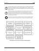
Introduction Block diagram of major steps for installation of Heated AOA/Pitot Probe AOA/Pitot Probe and Heated AOA/Pitot Probe Installation Guide Rev.
Introduction AOA Calculation: Principles of Operation Most pilots are introduced to the concept of angle of attack (AOA) during their initial flight training. However, as most GA aircraft do not provide a way to directly measure this critical flight parameter. WHAT IS ANGLE OF ATTACK, WHY IS IT IMPORTANT, AND WHO USES IT? Angle of attack is quite simply the angle between the wing chord and the oncoming air that the wing is flying through.
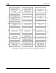
Introduction AIRFLOW: PRINCIPLES OF OPERATION The concept behind Dynon's design is illustrated in the diagrams at right. The Dynon Avionics AOA/Pitot probe performs two functions: airspeed sensing and angle of attack sensing. These functions require having two pressure ports on the tip of the probe. The normal pitot pressure port is on the front face of the probe and is designed to be insensitive to angle of attack.
Introduction starts as AOA becomes moderately high and increases in frequency until it is a solid tone very near the critical AOA. Heating: Principles of Operation Dynon Avionics Heated AOA/Pitot Probe utilizes a heating element whose temperature is accurately measured and regulated by a microprocessor-based controller. The controller monitors a temperature sensor embedded within the pitot body to regulate the heat for the front half of the Probe to a constant temperature.
2. TECHNICAL SERVICE BULLETIN FOR HEATED AOA/PITOT PROBE On May 6, 2014, Dynon Avionics issued a Technical Service Bulletin that discussed an issue with previously-manufactured Dynon Avionics Heated AOA/Pitot Probes (P/N 100667-000). It was subsequently updated in October 2014 with instructions to obtain a redesigned probe that fixes the identified issue. Customers that have Heated AOA/Pitot Probes that are affected by this Technical Service Bulletin should not proceed with installation.
Technical Service Bulletin for Heated AOA/Pitot Probe Heated AOA/Pitot Probe’s controller has its own unique serial number that cannot be used to identify affected Heated AOA/Pitot Probes. If your Heated AOA/Pitot Probe is replaced as part of the Technical Service Bulletin, after installing the replacement Heated AOA/Pitot Probe, you should re-perform the AOA Calibration procedures in your EFIS unit or SkyView System’s Installation Manual to ensure correct angle of attack is displayed.
3. HEATER CONTROLLER MOUNTING AND WIRING Please follow these instructions explicitly as improper installation can result in permanent damage to your device and/or aircraft. The Dynon Avionics Heated AOA/Pitot Probe operates on 12V only. For aircraft with a 24V electrical system, a 24V-to-12V DC-DC converter, capable of supplying 10A, must be used to supply the required 12V at 10A.
Heater Controller Mounting and Wiring Mounting the Controller The Heated AOA/Pitot Probe controller should ideally be mounted close to the Heated AOA/Pitot Probe on the underside of the wing to not require extending the included wires connecting the Probe to the controller. As with all avionics units, the controller should be mounted such that it can be accessed should service or replacement ever be required. The controller’s overall dimensions are: Width: 5.042” (128.07mm) Depth: 1.742” (44.
Heater Controller Mounting and Wiring All wires associated with the Dynon Avionics Heated AOA/Pitot Probe should have Tefzel insulation (Mil Standard M22759/16). To purchase such wire, specify M22759/16-xx where xx is the AWG size. For example, M22759/16-10 is 10 AWG wire with Tefzel insulation. We recommend that all wire used in your airplane have Tefzel insulation.
Heater Controller Mounting and Wiring 3-4 AOA/Pitot Probe and Heated AOA/Pitot Probe Installation Guide Rev.
Heater Controller Mounting and Wiring PROBE TO CONTROLLER WIRING As mentioned above, it is preferable that the Heated AOA/Pitot Probe controller be mounted close enough to the probe that 5 wires between the controller and probe can be connected without adding extension wiring. The three mating1 pairs of colored wires – terminated with Faston connectors – are used to carry the current to the heating element in the probe. The 2 white wires are for temperature measurement, and can thus be small.
Heater Controller Mounting and Wiring whenever the Probe’s heater is turned Off or is not functioning properly. While this is not required for Experimental and LSA category aircraft, this feature provides feedback that your Heated AOA/Pitot Probe is working as designed. The Heated AOA/Pitot Probe functions properly whether or not you make this connection - it is merely a status output for your convenience.
4. MOUNTING AND PLUMBING Tools and Materials Required Dynon Avionics AOA/Pitot probe or Dynon Avionics Heated AOA/Pitot Probe. AN5812 type mast for under-wing mounting o Models known to work can be found at http://wiki.dynonavionics.
Mounting and Plumbing MOUNTING INSTRUCTIONS After the mounting location has been determined, you will need to mount the pitot mounting kit per the included instructions or fabricate your own mount. In either case, mount the Dynon Avionics AOA/Pitot Probe / Heated AOA/Pitot Probe securely to rigid structure of the airframe. The body of the probe must be parallel to the wing chord. Use caution when drilling the holes, ensuring that you avoid drilling into the pitot and AOA pressure lines.
Mounting and Plumbing Dimensions In the following illustrations, only the pneumatic lines are shown for clarity. The external dimensions of the AOA/Pitot Probe and Heated AOA/Pitot Probe are identical. AOA/Pitot Probe and Heated AOA/Pitot Probe Installation Guide Rev.
Mounting and Plumbing Plumbing Because the pitot and AOA plumbing tubes have not been annealed, they workharden rapidly when manipulated. Make gentle bends, and only bend any given section once. It is acceptable to split the pitot input to both the Dynon Avionics EFIS unit / SkyView ADAHRS 200/201 and a standard airspeed indicator.
Mounting and Plumbing Although the Dynon Avionics AOA/Pitot Probe and Heated AOA/Pitot Probe incorporate a robust moisture separation and drainage design, the builder/installer should ensure that the design and installation of the overall AOA / Pitot system provides positive drainage of moisture from the entire AOA / Pitot / Static system.
5. ANGLE OF ATTACK CONFIGURATION AND CALIBRATION The Dynon Avionics AOA/Pitot Probe / Heated AOA/Pitot Probe is designed solely for use with Dynon Avionics EFIS units, Dynon Avionics SkyView system, and Advanced Flight Systems AOA and EFIS products. Installation manuals for all Dynon products can be found at http://docs.dynonavionics.com. Installation manuals for Advanced Flight Systems products can be found at http://advanced-flight-systems.com.
6. SPECIFICATIONS AOA/Pitot Probe P/N 100141-000 Weight:................................................................................................................... 0.35 lb. (0.18 kg) Tubing Connection: ........................................................................................... 3/16” OD aluminum Pitot Mounting: ............................................................................... AN5812 type mast (not provided) Moisture Protection:............................................