FlightDEK-D180 Installation Guide This product is not approved for installation in type certificated aircraft P/N 100600-000, Revision H For use with firmware version 5.4 August, 2010 Copyright © 2003-2010 by Dynon Avionics, Inc.
Contact Information Dynon Avionics, Inc. 19825 141st Place NE Woodinville, WA 98072 Phone: (425) 402-0433 - 7:00 AM – 5:00 PM (Pacific Time) Monday - Friday Fax: (425) 984-1751 Dynon Avionics offers online sales, extensive support, and continually-updated information on its products via its Internet sites: www.dynonavionics.com/support –Dynon Avionics primary web site; including: docs.dynonavionics.com – Current and archival documentation. downloads.dynonavionics.com – Software downloads.
Table of Contents Contact Information......................................................................................................................................................iii Copyright......................................................................................................................................................................iii Limited Warranty .............................................................................................................................
Table of Contents Compass Heading Calibration ................................................................................................................................... 5-1 Configure Airspeed Color Thresholds....................................................................................................................... 5-4 6. EMS Configuration 6-1 Full-Page Setup Menu Overview..................................................................................................................
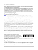
1. INTRODUCTION This manual provides information about the physical, electrical, and plumbing installation of the FlightDEK-D180, EDC-D10A, optional AOA pitot probe, and all engine sensors purchased from Dynon Avionics. Additionally, this guide deals with setting up the installation-dependant firmware options. Because you may not have purchased all the components, you need only read through the relevant sections of this guide.
Introduction About this Guide In the electronic (.PDF) version of this manual, page and section references in the Table of Contents and elsewhere act as hyperlinks taking you to the relevant location in the manual. The latest version of this manual is available on the Dynon Avionics website at docs.dynonavionics.com. The following icons are used in this guide: Any text following this icon describes functionality available only with the HS34 HSI Expansion Module connected to your system.
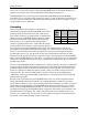
2. WIRING OVERVIEW Please follow these instructions explicitly as improper wiring can result in permanent damage to your instrument and/or the accompanying sensors. All electrical power and EFIS-specific lines interface with the FlightDEK-D180 via the female 25-pin D-sub connector on the back of the instrument. All EMS-related sensor inputs enter the FlightDEK-D180 via the male 37-pin and female 25-pin D-sub connectors on the back of the instrument.
Wiring Overview fuse for the wire you select. Power is fed to the FlightDEK-D180 via pins in the female D-25 connector as shown on the 25-Pin Female EFIS Harness diagram on page 2-4. The FlightDEK-D180 system-wide power requirement is 14 watts typical and 19 watts maximum. On a 12-volt system, this translates to about 1.5 amps of maximum current draw. On a 24-volt system, this translates to about 0.8 amps maximum current draw. Normally, a 3-amp circuit breaker or fuse is sufficient.
Wiring Overview +5V Excitation Some of the sensors require either a direct connection, or connection via a resistor, to the +5V excitation circuit. We recommend that you allow for more than one splice into this line. EMS DB37 Pin Color Function 18 White/red +5V excitation Thermocouple Harness Preparation Refer to the 25-Pin Male EMS Harness section on page 2-9 during this procedure. Strip 1” of brown outer insulation off each thermocouple wire pair on the supplied 25-pin thermocouple harness.
25-Pin Female EFIS Harness Below is the wiring diagram of the EFIS 25-pin female harness. If you purchased your harness from Dynon Avionics, it is color coded according to the chart on the following page. Unless noted otherwise, all wires are 3 feet long on the Dynon-provided harness.
The pin assignments for the female 25-pin harness are repeated below. Note that the pin numbers are labeled on the face of both the female and male connector. Each connection on the harness supplied by Dynon is color-coded. These colors are listed in the following chart.
Wiring Overview WIRING SYSTEM OVERVIEW The following block diagram depicts the basic layout of the EFIS DB25 electrical connections and is for reference only. Read the specific instructions for each connection prior to installation. The colors shown refer to the Dynon-supplied EFIS harness.
Wiring Overview 37-Pin Female EMS Harness Below is the wiring diagram of the EMS 37-pin female harness. If you purchased your harness from Dynon Avionics, pins 1, 2, 34, 35, 36, and 37 have wires inserted, but are not used. You may clip the wires or remove the pins as needed. Refer to the following page for detailed pin out descriptions.
Wiring Overview The pin assignments for the female 37-pin harness are repeated below. Note that the pin numbers are labeled on the face of both the female and male connector. Each connection on the harness supplied by Dynon is color-coded. These colors are listed in the following chart.
Wiring Overview 25-Pin Male EMS Harness Below is the EMS 25-pin harness wiring diagram. The 4-cylinder harness only has EGTs 1 through 4 and CHTs 1 through 4 wired. The Rotax harness only has EGTs 1 and 2 wired, as the EMS measures the Rotax-supplied resistive CHTs through its GP inputs. On the supplied harness, each pair of wires is encased in brown insulation and labeled with corresponding cylinder number. Inside the outer insulations, each wire in the pair has the color listed on the diagram below.
3. TRANSDUCER INSTALLATION This section explains the steps required to install and connect all transducers supplied by Dynon Avionics. Additionally, connection instructions are given for some transducers that Dynon Avionics does not sell, like the tachometer, fuel level, flaps, trim, and contacts. Tools and Equipment Required The following list contains commonly used tools and equipment; however some of the tools or equipment listed below may not apply to your installation.
Transducer Installation Exhaust Gas Temperature (EGT) Probes Correct placement of EGT probes on the exhaust manifold is critical to obtaining accurate readings. Placement differs between engine types, and even specific models. Consult your specific engine’s manual for proper EGT locations. ROTAX ENGINES For Rotax 912 engines, only two of the four cylinders are typically monitored for EGT.
Transducer Installation Cylinder Head Temperature (CHT) Probes Dynon Avionics sells and supports a variety of CHT probes. All thermocouple harnesses supplied by Dynon have each function (e.g., CHT1, EGT1) labeled on each thermocouple pair. LYCOMING/CONTINENTAL Dynon Avionics sells bayonet style CHT probes (used in Lycoming and Continental engines). With each probe we sell, a bayonet adapter is included.
Transducer Installation Tachometer Dynon Avionics does not sell a tachometer transducer. Pin 32 33 Color White/green White/blue Function RPM Left RPM Right Depending upon existing equipment and engine type, you have a few options for connecting the tachometer inputs on the FlightDEK-D180. See the relevant subsections below for your particular method. You may connect different types of signals to the two different RPM inputs (e.g., p-lead to RPM Left and a 12V transducer to RPM Right).
Transducer Installation brown, red, brown; connect in either direction). Connect the other end of the resistor to the RPM Left input on the FlightDEK-D180. ALTERNATOR WIRE (JABIRU) The most common tachometer pickoff location for Jabiru 2200 and 3300 engines is one of the alternator wires. Splice a wire off one of the two white alternator wires, connect it through a 1amp fuse to the RPM Left input on the FlightDEK-D180.
Transducer Installation If you notice fluctuations on the manifold pressure reading on the FlightDEK-D180, you may need to install a restrictor with a small hole inline between the sensor and the head where the manifold pressure line is split off. Oil Pressure Sensor The FlightDEK-D180 supports several oil pressure sensor installations. The Dynon-supplied sensor and the Rotax and Jabiru pre-installed sensors are the most common.
Transducer Installation Oil Temperature Sensor Pin Color The oil temperature sensor needs to be installed according to the directions of the engine 7 White/brown manufacturer. Dynon Avionics sells oil temperature sensors with both 5/8-18 UNF (Dynon P/N 100409-001) and 1/8-27 NPT (Dynon P/N 100409-000) threads. Ensure that you have the right sensor for your engine.
Transducer Installation are converting from a GRT EIS system, you must disconnect the external resistor pull-up from the fuel pressure output. This will make the sensor output equivalent to the sensor supplied by Dynon Avionics. Injected engines: Use the 0-80 PSI sensor (Dynon P/N 100411-001). Crimp a standard #8 ring terminal onto the brown wire from pin 8. Unscrew the stud cap from the threaded stud. Place the ring terminal on the stud and secure the cap down sandwiching the ring terminal.
Transducer Installation Fuel Flow Sensor Dynon Avionics supplies two different fuel flow transducers: Floscan 201B (Dynon P/N 100403-001) Electronics International FT-60 (Dynon P/N 100403003) GENERAL PLACEMENT RECOMMENDATIONS Pin 13 14 15 Color Function Black Ground Yellow (or Fuel flow white) input Fuel flow Red power (14V) When placing either sensor, ensure that the three wire leads are pointed straight up. A filter should be placed upstream from the sensor to screen out debris.
Transducer Installation 3-10 FlightDEK-D180 Installation Guide
Transducer Installation Fuel Level Sensor Dynon Avionics does not sell fuel level sensors. The FlightDEK-D180 supports both resistive type sensors as well as capacitive sensors which output a voltage (e.g., Princeton). If you have a capacitive sensor which does not output a voltage on its own, you may be able to use Dynon’s Capacitance-toVoltage Converter. Read the relevant section below for the type that you are installing.
Transducer Installation Ammeter Shunt The ammeter shunt should be mounted so that the metal part of the shunt cannot touch any part of the aircraft. The ammeter shunt can be installed in your electrical system in one of three locations as shown in the (simplified) electrical diagram below. Pin 24 25 Color Orange/green Orange/purple Function amps high amps low Position A: Ammeter indicates current flow into or out of your battery. In this position, it will show both positive and negative currents.
Transducer Installation FlightDEK-D180. These fusible links are a simple and cost-effective way to protect against short-circuits. Next, crimp the two supplied #8 ring terminals onto the wires using the fusing method chosen above. Connect the other ends of the fuses to the Amps High and Amps Low leads (pins 24 and 25) on the 37 pin harness. Unscrew the two smaller screws on the ammeter shunt. Slide the ring terminals onto them and screw them back into the base.
Transducer Installation the RV series, common locations include the wingtip and under the horizontal stabilizer. Avoid these three locations: Engine exhaust paths The engine itself Where the sensor will have direct sunlight Where the backside is exposed to a heated cabin Mounting Instructions After the mounting location has been determined, drill a 3/8” hole in the skin at the desired location. Uncoil the cable attached to the OAT probe. Remove the nylon nut from the cable.
Transducer Installation should find a 1kΩ resistor (color bands: brown, black, black, brown, brown; connect in either direction) in the package. Connect one end of this resistor to the +5V Excitation Circuit (pin 18) and the other end to the GP input you’ve connected the sensor to. If you received a sensor with black/white wires (Dynon P/N 100468), there will be no resistor in the package and you do not need to make any additional connections.
Transducer Installation TRIM AND FLAPS POSITION POTENTIOMETERS Dynon Avionics does not sell trim or flaps position sensors. These are normally included with, or added on to, their respective servos.
Transducer Installation pressure fitting with a restrictor hole in it. This restrictor hole ensures that, in the event of a sensor failure, coolant leakage rate is minimized, allowing time for an emergency landing. Crimp a standard ¼” female Faston onto one of the ground wires (see the Grounding section on page 2-2) +5V coming from the 37-pin harness.
Transducer Installation made between the wire and the connector (and resistor, if spliced in at that point). Unscrew the nut from the stud on the coolant temperature sensor. Slip the ring terminal onto the stud and secure the nut over it. Connect the other side of the 1kΩ resistor (color bands: brown, black, black, brown, brown; connect in either direction) to the 5V Excitation Circuit, pin 18, as shown in the diagram.
Transducer Installation General Purpose Thermocouple You may configure the FlightDEK-D180 to monitor one J or K type thermocouple. Dynon Avionics does not supply a specific general purpose thermocouple probe for this purpose. However, our standard EGT and CHT probes will work, as will any other J or K type thermocouple.
4. INSTRUMENT INSTALLATION This section provides you with the information needed to physically and electrically install the FlightDEK-D180. Selecting a Remote Compass Module Location Finding a good location for the EDC-D10A remote compass module is critical to an accurate FlightDEK-D180 heading display.
Instrument Installation if available, to make sure the EDC-D10A is aligned with the FlightDEK-D180 to better than 1 degree. All mounting hardware needs to be made from non-ferrous material such as aluminum, plastic, or brass. Many stainless steel screws are magnetic. If the item is attracted to a magnet, it should not be used in the installation. The EDC-D10A needs to be mounted in a location as free from magnetic interference as possible.
Instrument Installation turned on the heading display in the CLUTTR menu). If wiring is not correct, or the EDC-D10A is not communicating properly with the FlightDEK-D180, you will see the message REMOTE COMPASS NOT DETECTED in place of the heading onscreen. The metal shield around the EDC communication cable is connected to the short black/white wire emanating from the DB25. Connect this wire to ground. Power Inputs The FlightDEK-D180 has three separate power inputs, located on the EFIS connector.
Instrument Installation Serial Communication Cables More Information Is Available Online: Serial communication to non-Dynon devices, and interfacing of other devices in general can be involved and detailed. This Installation Guide is intended to provide general installation advice for the most common devices and situations. Dynon’s Documentation Wiki provides enhanced, extended, frequently updated online documentation contributed by Dynon employees and customers at wiki.dynonavionics.com.
Instrument Installation EFIS SERIAL HARNESS On the EFIS 25-pin wiring harness available from Dynon, there are three wires bundled together, terminating in a standard DB9-pin female connector. This cable is 6’ long and pre-assembled for connection to a PC-based laptop. Route this cable to a convenient location that can be accessed whenever you need to update your product’s firmware or checklists.
Instrument Installation SL30 and/or GPS connection Depending on the number and types of Dynon units you own, you have several options for connecting a GPS unit and/or Garmin/Apollo SL30 to your Dynon system. The GPS can be used as a data source for the EFIS, HSI, and Fuel pages, as well as Dynon’s EFIS-based Autopilot. The SL30 can be used as a VOR, localizer, or ILS (localizer + glideslope) source for the HSI.
Instrument Installation Read the section below that corresponds to your configuration of Dynon products. All EFISbased product configurations direct you to connect your external device to PC serial receive (pin 22) on your Dynon EFIS product. You may make this connection at any point between pin 22 on the EFIS DB25 and pin 3 on the connected DB9 EFIS/PC connector. If you purchased your harness from Dynon Avionics, it may have a yellow/green wire provided for this purpose.
Instrument Installation an SL30 connected, you are able to display an HSI on either product; with a GPS connected, you are able to display EMS fuel economy displays. If you have a GPS and an SL30, connect the GPS to pin 19 on the EMS DB37 connector. Connect the SL30 to pin 22 on the EFIS DB25 connector. This will allow you to flip between GPS and SL30 inputs. You can use either the SL30 or GPS as the NAV source on the EFIS product.
Instrument Installation system is displayed, push the following sequence of buttons: MORE > SETUP > MORE > ALTENC. When in the Altitude Encoder Setup menu, you can toggle the resolution of the output between 10 and 100 feet; this accommodates some transponders which can input and display altitude in 10 foot increments. In this menu, you can also select between the four different output formats, which are described below.
Instrument Installation External EMS Warning Light EMS DB37 Pin 29 can be wired and configured as an external warning light, or alternatively, to automatically control cabin light levels in sync with the screen brightness of the Dynon instruments. EMS DB37 Pin Color Function External warning light / Dimmer control 29 Yellow/Green To wire EMS DB37 Pin 29 as an external warning light, you may connect any standard LED or incandescent lamp (1.5 watts maximum), used during EMS-related alarm conditions.
Instrument Installation outputs, connect only its wire to the variable resistor. If you have purchased and installed an HS34 and/or an AP74, we recommend that you only connect the HS34 audio output or AP74 audio output (but not both) to your audio panel. The HS34 or AP74 audio output provides voice and tone outputs for both EMSand EFIS-related alerts. When the HS34 or AP74 audio output is connected, it is not necessary to connect the audio outputs of other Dynon Avionics devices.
Instrument Installation an EMS-series product, we recommend that you locate it in the middle of your wiring scheme as shown below. This eliminates the need to splice two wires together. Wherever possible, ensure that the two DSAB wires (DSAB A and B) are run as a twisted pair. This minimizes the system’s susceptibility to electrical noise. Refer to the DSAB Configuration chapter on page 7-1 for detailed instructions on configuring your DSAB network.
Instrument Installation Panel Location and Mounting The diagram below shows the outside dimensions of the front bezel of the FlightDEK-D180. Note that the instrument and tray extend about 4.5” behind the panel, and the supplied harness extends three inches more. Use the dimensions (in inches) found on the diagram to plan for the space required by the instrument. Take the following considerations into account when selecting a mounting location for the FlightDEK-D180.
Instrument Installation Connecting Static & Pitot Lines The AOA, pitot, and static ports on the back of the FlightDEK-D180 are equipped with 1/8” NPT Female fittings. To attach your pitot and static lines to the back of the FlightDEK-D180, you must use standard 1/8” NPT Male fittings at the end of each of the lines. To install, simply connect your static and pitot sources to the FlightDEK-D180, T’ing off of existing lines if performing a retrofit.
5. EFIS CALIBRATION AND CONFIGURATION During manufacture, your FlightDEK-D180 underwent a comprehensive calibration, verification, and burn-in routine that minimizes setup time and ensures that your EFIS meets Dynon’s stringent performance specifications. To account for your individual preferences and your aircraft’s particular setup, there are a few simple calibration and configuration steps that you must complete before using your FlightDEK-D180.
EFIS Calibration and Configuration SETTING MAGNETIC INCLINATION ANGLE AND INTENSITY (REQUIRED) To calibrate your FlightDEK-D180 heading, you must input your location’s current magnetic inclination angle and intensity. Before doing this, you must obtain these two values for the geographic location where you will be performing the calibration. Note that this procedure only needs to be done once, prior to magnetic calibration. Moving the aircraft to another location does not require repeating this procedure.
EFIS Calibration and Configuration EDC-D10A HEADING CALIBRATION (ON GROUND ONLY) The procedure for in-plane calibration of the EDC-D10A involves pointing the aircraft in four directions and taking data at each direction using the FlightDEK-D180. The FlightDEK-D180 will then perform some calculations to ensure an accurate calibration. During magnetic calibration, do not turn the power off on the FlightDEK-D180.
EFIS Calibration and Configuration take as long as 5 minutes. A message will be displayed onscreen: CALCULATING MAGNETIC CALIBRATION VALUES. 12. Wait for the message CALIBRATION COMPLETE before attempting to use the FlightDEK-D180 or remove power. Press BACK to leave the menu. This completes the EDC-D10A calibration process. The process can be repeated as often as desired.
EFIS Calibration and Configuration 3. Press BACK to return to the previous menu. You will not be able to see some of the colors until the aircraft has achieved airspeeds in the range of each threshold.
6. EMS CONFIGURATION Once the engine sensors are physically installed, you must configure the FlightDEK-D180 to recognize and correctly display all engine parameters. To interact with the FlightDEK-D180 menu system, use the 6 buttons on the front panel. The buttons are numbered one to six, left to right.
EMS Configuration for each function. The various supported sensors and their types are described below, starting at page 6-8. Alarm and Color Threshold Configuration In the various sensor setup menus, you will be configuring the alarms and color thresholds. Below is an introduction to the principles used. If you have configured EMS > GLOBAL > ENGINE TYPE to ROTAX, then the color thresholds for the Tachometer and Oil Temperature are automatically set in accordance with manufacturer specifications.
EMS Configuration When you modify one value, it will not “push” another value up or down. So, in the example above, you would not be able to increment the HI YEL/GRN parameter beyond 95 until you increased the HI RED/YEL parameter. Likewise, you would not be able decrement the HI RED/YEL value below 90 until you decrease the HI YEL/GRN parameter. To disable alarms before engine start, enter the EMS > SETUP > GLOBAL > ALARM CONFIG menu. Set PWR ON ALARMS to OFF.
EMS Configuration If you need to adjust the Hobbs time on the FlightDEK-D180 to match that of your engine, press DOWN▼ to select the item, SET HOBBS TIME. Press SEL► to enter the Hobbs time setting submenu. Press SEL► to select the desired digit and then DOWN▼ or UP▲ to change the value. When you are finished, press BACK. If you need to adjust the tachometer time on the FlightDEK-D180 to match that of your engine, press DOWN▼ to select the item, SET TACH TIME.
EMS Configuration 1400-1800 and 5500-5800 RPM in YELLOW 1800-5500 RPM in GREEN At 0 RPM, the LOW RPM ALARM is inhibited. When RPM advances above 0, the LOW RPM ALARM is inhibited for 10 seconds. The HIGH RPM ALARM is always active.
EMS Configuration Use the DOWN▼ or UP▲ buttons to select the tank that you wish to calibrate, and press SEL►. Enter the approximate number of gallons or liters the tank can hold. It is not necessary to be precise. This number is only used to determine reasonable fuel addition increments in the next steps. Press NEXT. Once you have confirmed that the tank you are calibrating is empty, press START. Follow the on-screen instructions until the completion of your fuel calibration.
EMS Configuration Once you are ready to calibrate, select the desired trim that you would like to calibrate, and press SEL► to enter its calibration menu. Press the RANGE button to begin calibrating the range of the trim. Follow the onscreen instructions, controlling trim to the required position before pressing NEXT. Repeat the process for the opposite position. The process will then prompt you to put the trim into takeoff position.
EMS Configuration Tachometer If you have connected a tachometer source to either the RPM Left or Right inputs, set the DISPLAY parameter to ON, otherwise, set it to OFF. Next, select whether the tachometer is to the left or right of the manifold pressure display. Simply select POSITION and press SEL► to toggle between LEFT and RIGHT. Select the alarm mode and the analog bar thresholds as described in Alarm and Color Threshold Configuration on page 6-2.
EMS Configuration sensor, you will be presented with the values AuxSF and AuxOff. You must enter these values according to the ones printed on your manifold pressure sensor, provided by GRT. Oil Pressure Select the alarm mode and the analog bar thresholds as described in Alarm and Color Threshold Configuration on page 6-2. If the oil pressure transducer has been installed, set the DISPLAY parameter to ON, otherwise, set it to OFF. Change the SENSOR TYPE to the correct number using the sensor type table.
EMS Configuration Exhaust Gas Temperature (EGT) Select the alarm mode and the analog bar thresholds as described in Alarm and Color Threshold Configuration on page 6-2. If one or more EGT thermocouples have been installed, set the DISPLAY parameter to ON; if no EGT thermocouples are installed, set it to OFF. There is no need to set a sensor type; any K-type thermocouple will work.
EMS Configuration Cylinder Head Temperature (CHT) Select the alarm mode and the analog bar thresholds as described in Alarm and Color Threshold Configuration on page 6-2. If one or more CHT sensors have been installed, set the DISPLAY parameter to ON; if no CHT sensors are installed, set it to OFF. If you are using Jtype thermocouples, you are finished with the CHT configuration; there is no need to configure a sensor type.
EMS Configuration cylinders’ CHTs is greater than the MAX SPAN value (or WHEN LEANING value, when leaning), a span alarm is triggered. When this occurs, those two CHT values will alternate between their actual value and a SPN alert. If you have configured the ALARM setting to either SELF-CLEAR or LATCHING, the SPN alarm will be red and will be accompanied by an alarm bar. If you have configured ALARM to be OFF, the SPN alarm will be yellow.
EMS Configuration Fuel Level If one or more fuel level transducers have been installed, set the DISPLAY parameter to ON; if no fuel level sensors are installed, set it to OFF. Select the alarm mode and the analog bar thresholds as described in Alarm and Color Threshold Configuration on page 6-2. You may select the on-screen names for the Tank 1 and Tank 2 inputs. You may choose from LEFT, MAIN, and TNK1 for Tank 1. You may choose from RIGHT, AUX, and TNK2 for Tank 2.
EMS Configuration Fuel Flow If the fuel flow transducer has been installed, set the DISPLAY parameter to either TEXT or DIAL. When set to TEXT, the fuel flow indication is displayed as a numerical value above a graphical fuel pressure dial. When set to DIAL, the opposite is true. Note that changing this value toggles the equivalent value in the FUEL PRESSURE menu.
EMS Configuration Voltage The voltmeter info item reports the voltage that the FlightDEK-D180 reads on its Master Power input (pin 1 on the EFIS 25-pin connector). Because of this, there is no sensor to install or configure. Simply, select the alarm mode and the analog bar thresholds as described in Alarm and Color Threshold Configuration on page 6-2.
EMS Configuration General Purpose Inputs In each of the 3 EMS GP INPUT submenus, you must select the function corresponding to the sensor that is installed for the respective GP connection. Ensure that you have configured your info items on the main and aux pages to display the desired GP inputs. Note that each GP menu will have help text, reading “DISPLAYED: INFO #” for each info item position where the given GP parameter is displayed.
EMS Configuration COOLANT TEMPERATURE Under the desired GP input number, set FUNCT to COOL TEMP. Select the analog bar thresholds as described in the Alarm and Color Threshold Configuration section on page 6-2. Set the SENSOR TYPE to the correct number using the sensor type table. COOLANT PRESSURE Under the desired GP input number, set FUNCT to COOL TEMP. Select the analog bar thresholds as described in the Alarm and Color Threshold Configuration section on page 6-2.
EMS Configuration GENERAL PURPOSE TEMPERATURE Under the desired GP input number, set FUNCT to GP TEMP. Select the analog bar thresholds as described in the Alarm and Color Threshold Configuration section on page 6-2. Set the SENSOR TYPE to the correct number using the sensor type table. Sensor Type GP Temp Sensor Dynon P/N 100433-000 (2-wire) Dynon P/N 100433-001 (3-wire, when installed as described on page 313) GRT OAT-01 1 Press DOWN▼ to select the LABEL 1 field.
EMS Configuration General Purpose Thermocouple Select the alarm mode as described in the Alarm and Color Threshold Configuration section on page 6-2. Configure the GP thermocouple info bar to display in the desired location(s), as described in the FlightDEK-D180 Pilot’s User Guide > Global Configuration Settings > Info Item Configuration section. Sensor Type J K GP Temp Sensor J Type Thermocouple K Type Thermocouple After configuring alarms, press DOWN▼ to select the LABEL 1 field.
7. DSAB CONFIGURATION This section introduces some concepts that are central to understanding and configuring a network of DSAB-capable Dynon products. It then takes you through a series of simple steps to configure your network, enabling data sharing and HS34 functionality. Do not proceed with DSAB configuration until you perform all installation, calibration, and configuration steps for each instrument with a display.
DSAB Configuration Example Networks The following two diagrams present example DSAB-connected networks. These examples illustrate and expand upon some of the concepts discussed above. The first diagram depicts a system without an HS34 connected, demonstrating where NAV and GPS devices should be connected. The second diagram depicts a system with an HS34 connected, demonstrating that all NAV and GPS devices must be connected to the HS34.
DSAB Configuration FlightDEK-D180 Installation Guide 7-3
DSAB Configuration Initial Setup As mentioned at the beginning of this chapter, configure your DSAB network only after all other installation steps have been performed, including updating all products to the latest version of firmware available from the Dynon Avionics web site at downloads.dynonavionics.com. To begin configuration, enter the EFIS > SETUP > DSAB menu. A full-page menu appears with three options: STATUS, CONFIGURATION, and BRIGHTNESS.
DSAB Configuration AP ROLL/PITCH SERVO Roll Servo and Pitch Servo functions are automatically detected and assigned during Autopilot Servo Calibration process. See: EFIS > SETUP > AP > SERVO CALIB. More than two SV32s or SV42s is not a supported configuration. If the configuration process could not automatically assign the EMS and OAT roles (because there are 2 or more of either type found on the network), it prompts you to assign each of them to the instrument of your choice.
DSAB Configuration Network Status The STATUS submenu displays information on all configured devices, their serial numbers, their roles on the network, and their status. The first line indicates how many devices are configured on the network. This number is independent of the number of devices actually currently turned on and communicating. It simply reports how many instruments were present during the most recent execution of DSAB configuration.
8. AUTOPILOT INSTALLATION AND CONFIGURATION Dynon Avionics’ Autopilot (AP) system is a competitively priced product for the Experimental & Light Sport Aircraft (LSA) aircraft market. Unlike standalone AP systems, Dynon’s AP is an enhancement to the Dynon Avionics EFIS-D10A, EFIS-D100, and FlightDEK-D180 products (beginning with firmware version 5.0).
Autopilot Installation and Configuration forum.dynonavionics.com – Dynon’s Online Customer Forum is a resource for Dynon Avionics customers to discuss installation and operational issues relating to Dynon Avionics products. The Forum is especially useful for pilots with uncommon aircraft or unusual installation issues. For customers that cannot call Dynon Technical Support during our normal business hours, the Forum is a convenient way to interact with Dynon Avionics Technical Support.
Autopilot Installation and Configuration Autopilot System Electrical Installation The diagram below provides an overview of the autopilot electrical system. The following sections describe the electrical installation of each subsystem in detail.
Autopilot Installation and Configuration SERVO ELECTRICAL INSTALLATION Dynon Avionics’ servos are supplied with 7 un-terminated wires, each about 8” in length. It is the responsibility of the installer to decide on connectors and associated wiring.
Autopilot Installation and Configuration AP CONTROLS ELECTRICAL INSTALLATION Circuit Breaker/Switch Install a circuit breaker or switch in a location that is accessible to the pilot while in flight. AP Disengage/Control Wheel Steering Button The AP Disengage/CWS button should be in a very accessible location, usually mounted to the stick or yoke. This button’s primary purpose is to immediately disengage the autopilot.
Autopilot Installation and Configuration Note: As with the optional Dynon HS34, it is acceptable to connect the tone output of EFIS (DB25 Pin 18) and/or EMS (DB37 Pin 31) in parallel with the tone/voice output of the AP74 (Pin 25) to provide “failover” audio alerts from the EFIS and/or EMS if the AP74 were to fail. However, do not connect the audio outputs from an HS34 and AP74 in parallel.
Autopilot Installation and Configuration or corner stock. Dynon recommends using 6061 T6 aluminum with a minimum thickness of 0.050” for the best balance of strength to weight. When fabricating a mounting bracket, refer to the servo dimensions below. Be sure to leave ample room for the arm and attached linkage to move through a complete range of motion without interference.
Autopilot Installation and Configuration PUSH-PULL SERVO DIMENSIONS Use the following dimensions (in inches) for reference when planning and implementing your installation. Long-arm variants (not needed in most installations) have linkage mount holes at 1.5”, 1.75”, and 2.0” L Weight SV32 2.17” 2 lb SV42 3.10” 3 lb SV52 4.
Autopilot Installation and Configuration LINKAGE MOUNT POSITION FORCE AND TRAVEL The two diagrams below illustrate the maximum travel and force available at each linkage mounting point. As can be seen, the closer you mount the linkage to the shaft, the more force the servo can deliver. However, this also means the travel of the arm is shorter. Again, ensure that the servo arm is nowhere near going over-center throughout the entire range of the control system. Standard Arm Max Linear Travel A: 2.6”, B: 2.
Autopilot Installation and Configuration the servo can exert, arm travel, control surface resolution, and the amount of force required to shear the brass shear screw. The two inner-most holes of the servo arm should only be used if the installer fully understands the resulting implications. The diagrams above illustrate the linear travel and available force for each mount point on the standard and long-arm servos.
Autopilot Installation and Configuration AP74 Mechanical Installation This section provides you with dimensions, panel location, and mounting information for the AP74 Dedicated Autopilot Interface. AP74 DIMENSIONS AND PANEL LOCATION The diagram below shows the AP74’s outer dimensions. Note that the instrument extends about 3.7” behind the panel, and that a harness can require up to three more inches. Use the dimensions (in inches) found on the diagram to plan for the space required by the instrument.
Autopilot Installation and Configuration MOUNTING BRACKET DIMENSIONS The dimensions for the included mounting bracket are below. This bracket will work with varying panel thicknesses in both vertical and horizontal orientations. The primary force used to secure the instrument to a panel is the “sandwich” action of tightening the bracket behind through to the instrument bezel in front. The bracket includes a small mounting flange that can be used to positively secure the bracket to the panel if desired.
Autopilot Installation and Configuration AP74 MOUNTING As shown in diagram below, make a rectangular cutout (oriented either vertically or horizontally, depending on instrument version ordered) of 1.45” by 4.75” (3.69 cm by 12.07 cm). Your AP74 also shipped with a life-sized mounting template for making this cutout and locating the optional mounting flange holes. If the flange is used, secure it to your panel in whatever way you desire.
Autopilot Installation and Configuration Detailed instructions for performing firmware upgrades are contained in the “Help” function of the Dynon Avionics Product Support Program which is available on the Dynon Avionics web site at downloads.dynonavionics.com. If you are using a GPS connected to your Dynon EFIS and will be using GPS as an input for the AP, please upgrade your GPS to the most current firmware available for it.
Autopilot Installation and Configuration Enter the EFIS > SETUP > DSAB > CONFIGURATION menu. ARE YOU SURE YOU WANT TO RE-CONFIGURE THE NETWORK? Press YES ARE ALL NETWORKED DEVICES POWERED ON? Press CONFIGURE NOW PLEASE WAIT DETECTING ALL NETWORK DEVICES Wait up to 1 minute (X) DEVICES FOUND NETWORK CONFIGURATION IS COMPLETE Verify that this shows the correct number of devices. If not, check wiring and ensure that all expected devices are powered on.
Autopilot Installation and Configuration 2 SERVO(S) FOUND PLEASE CENTER ALL CONTROL SURFACES AND MAKE SURE THEY HAVE A FREE RANGE OF MOTION. PRESS DISCONNECT SWITCH TO CONTINUE. Follow all onscreen instructions, moving the controls to each position, pressing the Disengage/CWS Button to confirm each position. This process calibrates the autopilot to detect the orientation and range of each servo. If calibration was successful: CALIBRATION WAS SUCCESSFUL. ROLL FOUND. PITCH FOUND.
Autopilot Installation and Configuration STEP 3 - ROLL SERVO INITIAL SETUP We recommend that you perform the following on the ground at zero airspeed. Step 3a – Set Roll Servo Torque: The ROLL SERVO > TORQUE parameter specifies how much torque the servos will exert before slipping. Servo slip is indicated by a yellow background on the slipping axis in the AP status indicator.
Autopilot Installation and Configuration DOWN▼ > (SENSITIVITY value is highlighted) Press DEC - and INC + to adjust SENSITIVITY to preferred initial setting for the aircraft. Step 3c – Set Roll Servo Turn Rate Limit: The ROLL SERVO > TRN RT LMT parameter specifies the desired average turn rate for AP-commanded turns. For example, a setting of 3.0°/S will ideally complete a 90° turn in 30 seconds.
Autopilot Installation and Configuration loads, but low enough that the pilot can override the AP should the need arise. If the servo slips continuously, the AP cannot fly the aircraft. Torque is specified in % of maximum the servo is capable of exerting. Minimum: 10%, maximum 100%, default: 100%.
Autopilot Installation and Configuration Altitude Gain (ALT GAIN): Use only after sensitivity and all of the above settings are set as well as they can be. Increase gradually if airplane levels off too soon. Reduce gradually if airplane overshoots altitudes after climbs and descents. The default setting is 6. Pull Rate: Use only after sensitivity and all of the above settings are set as well as they can be. Controls the rate the AP will push or pull when changing vertical speed.
Autopilot Installation and Configuration MAX AIRSPEED – REDUCE POWER Airspeed Maximum is specified in knots, kilometers/hr, or miles/hr, depending on the units chosen in the EFIS > SETUP > UNITS > IAS menu. Maximum/default: 5% below V NE . To set the AIRSP MAX, perform the following (continuing from AIRSP MIN): DOWN▼ > (AIRSP MAX: value is highlighted) Press DEC - and INC + to adjust APRSP MAX to preferred initial setting for the aircraft.
Autopilot Installation and Configuration Disengage/CWS Button while flying to a new heading and/or altitude, then release the button to reengage the Autopilot. The Autopilot will reengage in the mode set by the MODE parameter, described below. Default is N On the EFIS, perform the following (continuing from Button Configuration Resistor Installed): DOWN▼ > (-CTRL WHEEL STEER- ENABLED: value is highlighted) SEL► > Set to Y or N per the explanation above.
Autopilot Installation and Configuration STEP 6 - AUDIO ALERTS CONFIGURATION This section applies only if you have installed the optional AP74. The optional AP74 can act as the sole audio alert source for all DSAB-connected Dynon instruments. The audio output of the AP74 reports both EFIS and EMS alerts; each type of alert can be configured to be either voice or tone formats. When the AP74 is connected to your system, audible alerts are still generated by both EMS- and EFIS-based instruments.
Autopilot Installation and Configuration through the “direct” audio output of the EFIS and the audio output of the AP74 is muted. * If an AP74 failure is detected during this condition, the EFIS “direct” audio output (tones only) is automatically re-enabled (fail-over). Selecting TEST VOICE OUTPUT and then pressing SEL► produces an audible voice test (“DYNON AVIONICS”) on the audio output line. This allows you to verify connections and volume on the ground.
Autopilot Installation and Configuration STEP 8 – ROLL SERVO FLIGHT TUNING This set of procedures tunes the settings in the AP > ROLL SERVO menu for the particular flight characteristics of the aircraft in heading holds and turns.
Autopilot Installation and Configuration If you have adjusted the roll servo TORQUE value to 100% and are still seeing frequent slips, you may need to move the linkage attachment point on the roll servo 1 hole closer to the shaft. When doing this, take all precautions to ensure that an over center condition cannot occur, while still preserving the control surfaces’ full range of motion. If a mechanical solution is not possible, you may wish to try a higher strength servo (e.g.
Autopilot Installation and Configuration Step 8h – Verify TRN RT LMT and BANK LIMIT settings during turn(s) During an AP-commanded turn, verify that the time to complete a turn matches your expectations given the setting for the TRN RT LMT parameter. For example, when TRN RT LMT is set to 3º/s, a 90º turn should take about 30 seconds. If this is not the case, the bank angle required by the target turn rate may exceed the set BANK LIMIT parameter.
Autopilot Installation and Configuration Step 9d – Allow a few minutes of stable flight under AP control Note that the AP is only flying in Altitude Hold Mode, so you will need to control the aircraft in roll. Ensure that you are not affecting the Autopilot’s control of the pitch axis, so you can determine the AP’s altitude hold and change performance.
Autopilot Installation and Configuration Repeat the AP-commanded climbs/descents and torque adjustments until the ALT indicator does not display a slip indication. Continue performing AP-commanded climbs and descents, and observe the overall behavior of the aircraft. If the aircraft oscillates in holds or overshoots as it reaches target altitude, that is an indication that the Pitch Servo SENSITIVITY needs to be increased.
Autopilot Installation and Configuration STEP 10 – VERIFY OVERALL AP PERFORMANCE Engage both roll and pitch servos and execute a number of AP-controlled changes of heading, altitude, and combinations of the two and observe the overall aircraft performance under AP control. There may be some interaction between the various Pitch Servo and Roll Servo settings. Repeat portions of steps 9 and 10 as necessary to fully “dial in” the AP for overall smooth flight performance under AP control.
Autopilot Installation and Configuration PRE-SELECT CONFIGURATION In the -BUGS- section of the AP74/76 SETTINGS menu, you can choose when the heading and altitude bugs should be synchronized to their respective current values: ON ENGAGE: The HDG and ALT bugs are synchronized to the heading and altitude values each time the AP is engaged (via the AP button on the AP74 or in the EFIS AP menu). This is the default setting.
9. APPENDIX The appendices contain additional information pertaining to the installation of the FlightDEKD180. You will find here a table of weights, specifications, the maintenance manual, the OAT Installation and Operating Guide, the AOA Pitot Installation Guide, and the Blind encoder Serial-to-Gray Code Installation Guide. Appendix A: Ongoing Maintenance and Troubleshooting INTRODUCTION This section gives the installer or mechanic information pertaining to maintenance of the FlightDEK-D180.
Appendix in the menu system. The battery may charge to as high as 16.8 volts, but it is only necessary to charge it to 16.0 volts for this test. 2. Remove all sources of external power from the FlightDEK-D180, ensuring that it is operating off its internal battery. 3. Ensure that the screen is at its full brightness level.
Appendix DISPLAYED ALERT MESSAGES The following table describes the alert messages that the FlightDEK-D180 can display. Alert Message INTERNAL ERROR SERVICE UNIT Description This error can occur for a few reasons, including an aborted upload. It signifies that the FlightDEK-D180 has detected internal problems in its firmware or calibration tables.
Appendix Alert Message INTERNAL BATTERY LOW Description You will see this alert only when operating the unit solely off the internal backup battery. When its voltage has dropped below a certain threshold, you will see this alert. Additionally, the voltmeter will be displayed onscreen. When you see this alert, it is advisable that you turn the unit off by pressing the POWER button in Main Menu 1. REMOTE COMPASS NOT DETECTED The FlightDEK-D180 is unable to communicate with the EDC-D10A.
Appendix Problem After performing a magnetic calibration the FlightDEKD180‘s heading is wrong by a constant amount. When the barometer on the unit is set correctly, the displayed altitude is wrong by a constant amount at all altitudes. Airspeed is inaccurate by between 1 and 10 knots (or equivalent, in other units) at takeoff speed.
Appendix Problem Internal battery life is too short Clock setting is lost Cannot make connection with PC Unit will not boot off battery power Solution Verify internal battery is charged to above 16 volts using FlightDEK-D180 voltmeter. Re-run capacity test. Replace battery if insufficient capacity. If present, verify internal battery is charged. If no internal battery, verify Keep Alive power is supplied to unit at all times. Verify wiring is correct.
Appendix Appendix B: Dynon EFIS OAT Probe Installation and Usage Note that this section only applies to the OAT with 3 wires (colored red, yellow, and blue), for connection to the EDC-D10A. If you have the 2-wire EMS OAT connected to the DB37 connector, you do not need to also have the EFIS OAT connected. See the Outside Air Temperature Sensor installation section on page 3-13 for information on installing the 2-wire OAT. Ensure that no EMS GP input is configured as an OAT.
Appendix end of the OAT probe. Spread some Loctite around the threads of the OAT probe. Twist the nut onto the threads of the OAT probe and tighten. Wiring Instructions. Once you have physically mounted the OAT probe, route its attached cable to the EDC-D10A remote magnetic compass module. Your OAT comes with pins crimped on the 3 wires. Insert these 3 wires’ pins to the following pin numbers on the D9 which plugs into the EDC-D10A. The front of the female connector is pictured at right.
Appendix CALIBRATION AND ADJUSTMENT Before calibration or adjustment, it is possible for the OAT sensor to read as much as 5 degrees Celsius off the actual value. Therefore, it may be necessary to adjust the displayed air temperature value to compensate for this. To make this adjustment, you must enter the menu system and press the following sequence of buttons: MORE > SETUP > MORE > OAT. This will display the OAT adjustment menu. Press INC or DEC to increase or decrease the currently displayed OAT value.
Appendix Appendix C: HS34 Installation and Configuration If you purchased an HS34 from Dynon Avionics, read through this section for details on its physical and electrical installation. It describes the pinout, mounting information, and some common wiring connections. WIRING Follow these instructions explicitly as improper wiring can result in permanent damage to your instrument, other connected equipment, or both. Read through the Recommended Wiring Practices section on page 2-1 before proceeding.
Appendix Pinouts and Function Description Below are the pinouts and function descriptions for the HS34’s male and female connectors. At a minimum, you must make the connections shown in the Universal Connections diagram. All other wiring connections depend on the external equipment you are connecting to the HS34. Many common radio and GPS connections are depicted in the Common Device Connections section below. Note that the pin numbers are labeled on the face of both the female and male connector.
Appendix Universal Connections The following diagram shows the wiring connections that must be made in every HS34 installation. These required connections ensure that the HS34 can power on, communicate with other Dynon products, connect to a laptop for firmware uploads, and output audio alerts to your intercom system. Once properly configured on your DSAB network, this connection scheme allows you to use your HS34’s VALUE knob with the DSAB Bus Master.
Appendix Generic Device Connections The three diagrams on this page depict generic device connections for devices outputting ARINC, serial, or analog data. If your device outputs multiple types of data, connect only one type to the HS34 in the following preference: ARINC preferred over serial; serial preferred over analog. ARINC data streams contain more information (vertical GPS guidance, GPS steering, etc) than serial streams and allow more control of your external device.
Appendix Common Device Connections The following several diagrams show some common radios and GPSs, and the preferred connection schemes between them and the HS34. Make note of whether the connections are to the male or female connector on the back of the HS34. When constructing your harness, refer to the pinouts on page 9-11.
Appendix FlightDEK-D180 Installation Guide 9-15
Appendix 9-16 FlightDEK-D180 Installation Guide
Appendix PANEL LOCATION AND MOUNTING This section provides you with dimensions, panel location, and mounting information. HS34 Dimensions and Panel Location The diagram below shows the HS34’s outer dimensions. Note that the instrument extends about 3.7” behind the panel, and that harnesses can require up to three more inches. Use the dimensions (in inches) found on the diagram to plan for the space required by the instrument.
Appendix Mounting Tab Dimensions The dimensions for the included mounting tab are below. Note that the tab does not extend behind the panel perpendicularly. This sharper angle causes the HS34 to pull itself against the panel when screwed into the tab. HS34 Mounting As shown in diagram at right, make a rectangular cutout – oriented either vertically or horizontally, depending on HS34 version ordered – of 1.45” by 4.75” (3.69 cm by 12.07 cm). Drill three holes at the locations specified in the diagram.
Appendix HS34 CONFIGURATION This section guides you through configuring your HS34. Prior to beginning this section, you must have completed all the steps in the DSAB Configuration chapter with the HS34 turned on and connected to the DSAB network. After DSAB configuration, ensure that the HS34 appears as one of the ACTIVE devices in the EFIS > SETUP > DSAB > STATUS menu. You may only configure your HS34 on the EFIS-based instrument assigned the DSAB Bus Master role.
Appendix Markers Configuration The HS34 supports markers input via ARINC or the 3 discrete Inner, Middle, and Outer marker pins. If your NAV radio outputs ARINC data whose stream contains marker information, set the SOURCE to either ARINC1 or ARINC2. ARINC1 corresponds to the ARINC-429 RX 1 A and B inputs (female DB25, pins 11 and 23). ARINC2 corresponds to the ARINC-429 RX 2 A and B inputs (female DB25, pins 10 and 22).
Appendix the input you wish to be assigned NAV2 in the source cycle, and so on for as many other NAV radio inputs. Repeat the above procedure for all configured GPS inputs in the GPS ORDER menu. Voice/Tone Alert Configuration The HS34 can act as the sole audio alert source for all DSAB-connected Dynon instruments. The HS34’s audio output reports both EFIS and EMS alerts; each type of alert can be configured to be either voice or tone formats.
Appendix * If an HS34 failure is detected during this condition, the EFIS “direct” audio output (tones only) is automatically re-enabled (fail-over). Selecting TEST VOICE OUTPUT and then pressing SEL► produces an audible voice test (“DYNON AVIONICS”) on the audio output line. This allows you to verify connections and volume on the ground. The possible voice alerts for both EFIS and EMS are listed in the table above.
Appendix NAV and/or GPS Fail-over While not required, it is possible to provide a NAV and/or GPS data fail-over capability in case of a failure of the HS34. To accomplish this, the outputs of the NAV and/or GPS device can be connected in parallel to an EFIS or EMS and an HS34. While the HS34 is operating normally, the NAV and/or GPS data connected to the HS34 is displayed. (Only) if the HS34 fails, the NAV and/or GPS data connected to the EFIS and/or EMS is (temporarily) displayed.
Appendix Appendix D: Dynon AOA/Pitot Installation and Calibration Thank you for your purchase of Dynon’s AOA/Pitot Probe. This guide walks you through the steps to install and calibrate both the heated and unheated versions of the AOA/Pitot Probe. While the probe senses standard pitot pressure, allowing it to work with any standard airspeed indicator, its AOA functionality is designed specifically to work with Dynon’s EFIS series of products. Do not expect it to work properly with another AOA system.
Appendix TOOLS AND MATERIALS REQUIRED Dynon Avionics AOA/Pitot probe. Two plumbing lines (usually ¼” soft aluminum or plastic tubing) routed from the FlightDEK-D180 to the probe mounting location. Tubing interface hardware o Reference our wiki at wiki.dynonavionics.com for tubing interface hardware recommendations. #36 Drill and 6-32 tap AOA Pitot Mounting bracket. Models known to work well include: o Gretz Aero CBK12 (Chrome) and PBK12 (Paintable), available at gretzaero.com/mountbracket.
Appendix Heated AOA/Pitot Wiring System Overview The following block diagram depicts the basic layout of the electrical connections between the probe and heater controller. This diagram should be used in conjunction with detailed instructions on the following pages. Read the specific instructions for each connection prior to installation.
Appendix Heater Controller Wiring Before making the connections to your Heated AOA/Pitot Probe and controller, refer to the Recommended Wiring Practices section on page 2-1. The chart at right provides general recommendations for wire gauge choice, given wiring run length.
Appendix controller. Remember that even when the controller is powered on, it only heats the probe the amount necessary to maintain temperature. The black wire should be permanently connected to ground. Cutting power to the heater controller should occur via the red power line, not the black ground line. Heater Status Connection Note: The probe heater functions properly whether or not you make this connection. It is simply a status output for your convenience.
Appendix these lines, you may drill all the way through the outer metal without affecting the probe’s waterproofing.
Appendix Boom mount PLUMBING NOTE: Because the pitot and AOA plumbing tubes have not been annealed, they work-harden rapidly when manipulated. Make gentle bends, and only bend any given section once. After mounting the probe, route the pitot and AOA lines from the probe to your FlightDEKD180. The tube closest to the snout is the pitot line, while the tube in the rear is the AOA line. There is no static source on the probe.
Appendix flight regimes not listed that you suspect would create stalls at lower angle of attack it would be good to record those as well. With full power, no flaps With no power, no flaps With full power, full flaps With no power, full flaps Push the STALL button before performing each stall. When you push the STALL button, a 45second timer starts. Notice the “T” next to the time that is counting down.
Appendix Appendix E: Encoder Serial-to-Gray Code Converter Installation INTRODUCTION AND DESCRIPTION The Encoder Converter is an electronic device that receives the serial encoder data from the FlightDEK-D180 and outputs standard Mode-C parallel Gray code into your Mode-C transponder. This Encoder Converter requires data from the FlightDEK-D180 and is not to be confused with other standalone encoders available on the market.
Appendix directly to your switched avionics power. Ensure that all avionics power is off before performing the wiring step of this installation. If your Altitude Transponder has either a strobe signal or a D4 pin, leave these pins unconnected.
Appendix EFIS DB25 Pin# 13 21 Dynon EFIS harness color Blue/White (may be black on some harnesses) White Encoder Converter Wire Color Function Green (May be Red on older models) Serial Encoder Transmit Black Serial Encoder Ground STEP 3: FLIGHTDEK-D180 ENCODER FORMAT For proper communication the EFIS Altitude Encoder format must be set to format number one. To change this setting, from the main menu, select: MORE > SETUP > MORE > ALTENC. Press FRMAT until it reads “1.
Appendix Appendix F: Capacitance-to-Voltage Converter Installation Dynon Avionics’ capacitance-to-voltage converter is suitable for general use with most capacitive plate fuel level sensors. It accepts an input via a female BNC and outputs a dc voltage signal that can be read by the FlightDEK-D180. It requires 10 Vdc to 15 Vdc for power and draws minimal current.
Appendix Appendix G: Replacing the FlightDEK-D180 battery pack 1. Remove the two screws (either #1 Phillips or 7/64” hex, depending on when your unit was manufactured) from the small, rectangular battery door on the side of the FlightDEKD180. Remove the battery door. Do not remove any other screws from the case of the unit. 2. If you previously had a battery, disconnect it from the FlightDEK-D180 by unplugging the battery connector and gently pulling out old battery.
Appendix OAT sender.................................................................................................................3 oz (0.09 kg) Fuel flow sender..........................................................................................................4 oz (0.11 kg) Carburetor temperature sender....................................................................................2 oz (0.06 kg) Ammeter shunt.......................................................................................
Appendix Appendix I: FlightDEK-D180 Specifications Mechanical Operating Temperature Power Connections Screen Sensor Inputs Inputs/Outputs 9-38 6.95” wide x 4.90” tall x 4.51” deep (177 x 125 x 115 mm) -22° to 122° F (-30° to 50° C) Voltage: Power: 10 - 30 Vdc 14 watts typical; 19 watts maximum Wiring: DB25 female, DB25 male & DB37 male connectors Type: Backlight: Size: Resolution: AMLCD, TFT (Thin Film Transistor) 400 nits (or 800 nits, for super-bright option) 7.