
Installation Guide Owner manual

EMS Configuration
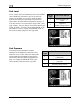
Voltage
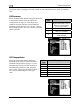
The voltmeter info item reports the voltage that the EMS-D10 reads on its Master Power input
(pin 1 on the EMS 37-pin connector). Because of this, there is no sensor to install or configure.
Simply, select the alarm mode and the analog bar thresholds as described in Alarm and Color
Threshold C
onfiguration on page 5-2. Configure the voltmeter info bar to display in the desired
location(s
), as described in the EMS-D10 Pilot’s User Guide > Global Configuration Settings >
Info Item Configuration
section.
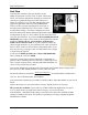
Current
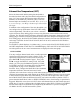
If a current sensor has been installed, set the DISPLAY
parameter to ON, otherwise, set it to OFF. First, select
whether your ammeter will be showing positive and
negative currents (-60A TO 60A; used for Location A)
or only positive currents (0A TO 60A; used for
Locations B and C). This will depend on your
installation as mentioned in the Ammeter Shunt installation
section on page 3-12. Select the alarm mode and the analog
bar thresholds as described in Alarm and Color Threshold
Configuration on page 5-2. Change the SENSOR TYPE to
the correct num
ber using the sensor type table. Configure
the ammeter info bar to display in the desired location(s), as
described in the EMS-D10 Pilot’s User Guide > Global
Configuration Settings > Info Item Configuration
section.
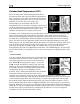
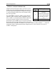
Sensor
Type
Ammeter Sensor
1 Dynon P/N 100412-000
2 GRT CS-01
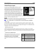
If you are using the GRT CS-01 Hall effect sensor, you m
ay
need to set the zero-point of the sensor. After you have selected a SENSOR TYPE of “2,” the
OFFSET parameter will be displayed. Adjust the OFFSET (in increments of 1 amp) until the
current displayed on the EMS Main page screen is correct at a known current.
EMS-D10 Installation Guide 5-15