
Installation Guide Owner manual


Wiring Overview
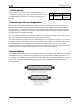
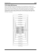
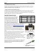
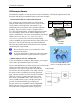
25-Pin Male EMS Harness
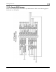
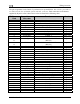
Below is the EMS 25-pin harness wiring diagram. The 4-cylinder harness only has EGTs 1
through 4 and CHTs 1 through 4 wired. The Rotax harness only has EGTs 1 and 2 wired, as the
EMS measures the Rotax-supplied resistive CHTs through its GP inputs. On the supplied
harness, each pair of wires is encased in brown insulation and labeled with corresponding
cylinder number. Inside the outer insulations, each wire in the pair has the color listed on the
diagram below. If you are making your own harness, utilize J & K type thermocouple wire as
indicated in the diagram.
2-6 EMS-D10 Installation Guide