
Installation Guide Owner manual
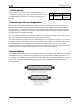


Wiring Overview
EMS-D10 Installation Guide 2-5
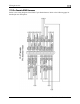
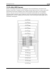
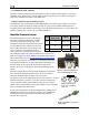
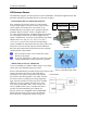
The pin assignments for the female 37-pin harness are repeated below. Note that the pin numbers
are labeled on the face of both the female and male connector. Each connection on the harness
supplied by Dynon is color-coded. These colors are listed in the following chart.
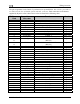
DB37 harness
Pin#
Dynon Harness
Wire color
Function Details
1 Red Master Power (10-30V) Page 4-1
2 Yellow Keep Alive (10-30V, low current) Page 4-1
3 Black Master Ground Page 2-2
4 Purple/blue GP 1 (general purpose resistive) Page 3-13
5 Black Ground Page 2-2
6 White/yellow Oil pressure Page 3-6
7 White/brown Oil temperature Page 3-6
8 Brown Fuel pressure Page 3-7
9 Brown/blue Contact 1 Page 3-18
10 Brown/yellow Contact 2 Page 3-18
11
Orange EMS-D10 Transmit / PC Serial Receive
(RS-232)
Page 4-2
12
Yellow EMS-D10 Receive / PC Serial Transmit
(RS-232)
Page 4-2
13 Black Ground (Fuel Flow) Page 3-9
14 Yellow Fuel flow input Page 3-9
15 Red Fuel flow power (12V) Page 3-9
16 Black Ground Page 2-2
17 Black Ground Page 2-2
18 White/red 5V excitation circuit Page 2-2
19 White/black Auxiliary Serial Receive (RS-232) Page 4-2
20 Orange/brown Fuel level 1 Page 3-11
21 Orange/blue Fuel level 2 Page 3-11
22 Purple/yellow GP 2 (General Purpose Resistive) Page 3-13
23 Purple/green GP 3 (General Purpose Resistive) Page 3-13
24 Orange/green Amps High Page 3-12
25 Orange/purple Amps Low Page 3-12
26 Green/red Manifold pressure Page 3-5
27
Not supplied
General purpose thermocouple (J or K-type) Page 3-18
28
Not supplied
General purpose thermocouple (J or K-type) Page 3-18
29 Yellow/green External warning light Page 4-2
30 Black PC Serial ground Page 4-2
31 White/orange Intercom audio alert Page 4-2
32 White/green RPM left Page 3-4
33 White/blue RPM right Page 3-4
34 Blue DSAB B Page 4-7
35 Green DSAB A Page 4-7
36 Blue DSAB B Page 4-7
37 Green DSAB A Page 4-7