EMS-D10 Installation Guide This product is not approved for installation in type certificated aircraft P/N 100430-000, Revision I For use with firmware version 5.4 August, 2010 Copyright © 2003-2010 by Dynon Avionics, Inc.
Contact Information Dynon Avionics, Inc. 19825 141st Place NE Woodinville, WA 98072 Phone: (425) 402-0433 - 7:00 AM – 5:00 PM (Pacific Time) Monday - Friday Fax: (425) 984-1751 Dynon Avionics offers online sales, extensive support, and continually-updated information on its products via its Internet sites: www.dynonavionics.com/support –Dynon Avionics primary web site; including: docs.dynonavionics.com – Current and archival documentation. downloads.dynonavionics.com – Software downloads.
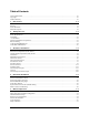
Table of Contents Contact Information......................................................................................................................................................iii Copyright......................................................................................................................................................................iii Limited Warranty .............................................................................................................................
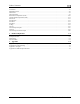
Table of Contents Tachometer ................................................................................................................................................................ 5-8 Manifold Pressure...................................................................................................................................................... 5-8 Oil Pressure .....................................................................................................................................
1. INTRODUCTION This manual provides information about the physical and electrical installation of the EMS-D10 and connected sensors. Additionally, this guide deals with setting up the installation-dependant firmware options. Because you may not have purchased all the components, you need only read through the relevant sections of this guide. Information about the operation of this instrument can be found in the EMS-D10 Pilot’s User Guide.
Introduction About this Guide In the electronic (.PDF) version of this manual, page and section references in the Table of Contents and elsewhere act as hyperlinks taking you to the relevant location in the manual. The latest version of this manual is available on the Dynon Avionics website at docs.dynonavionics.com. The following icons are used in this guide: Any text following this icon describes functionality available only with the HS34 HSI Expansion Module connected to your system.
2. WIRING OVERVIEW Please follow these instructions explicitly as improper wiring can result in permanent damage to your instrument and/or the accompanying sensors. All electrical power and data lines interface with the EMS-D10 via the male 37-pin D-Sub connector on the back of the unit. EGT (exhaust gas temperature) and CHT (cylinder head temperature) thermocouple inputs enter the unit via the female 25-pin D-Sub connector.
Wiring Overview particular aircraft. Ensure that the power lines include a circuit breaker or an appropriately sized fuse for the wire you select. The EMS-D10 system-wide power requirement is 8 watts typical and 10 watts maximum. On a 12-volt system, this translates to about 1 amp of maximum current draw. On a 24-volt system, this translates to about 0.5 amps maximum current draw. Normally, a 2-amp circuit breaker or fuse is sufficient.
Wiring Overview +5V Excitation Some of the sensors require either a direct connection, or connection via a resistor, to the +5V excitation circuit. We recommend that you allow for more than one splice into this line. Pin Color 18 White/red Function +5V excitation Thermocouple Harness Preparation Refer to the 25-Pin Male EMS Harness section on page 2-6 during this procedure. Strip 1” of brown outer insulation off each thermocouple wire pair on the supplied 25-pin thermocouple harness.
Wiring Overview 37-Pin Female EMS Harness Below is the wiring diagram of the EMS 37-pin female harness. Refer to the following page for detailed pin out descriptions.
Wiring Overview The pin assignments for the female 37-pin harness are repeated below. Note that the pin numbers are labeled on the face of both the female and male connector. Each connection on the harness supplied by Dynon is color-coded. These colors are listed in the following chart.
Wiring Overview 25-Pin Male EMS Harness Below is the EMS 25-pin harness wiring diagram. The 4-cylinder harness only has EGTs 1 through 4 and CHTs 1 through 4 wired. The Rotax harness only has EGTs 1 and 2 wired, as the EMS measures the Rotax-supplied resistive CHTs through its GP inputs. On the supplied harness, each pair of wires is encased in brown insulation and labeled with corresponding cylinder number. Inside the outer insulations, each wire in the pair has the color listed on the diagram below.
3. TRANSDUCER INSTALLATION This section explains the steps required to install and connect all transducers supplied by Dynon Avionics. Additionally, connection instructions are given for some transducers that Dynon Avionics does not sell, like the tachometer, fuel level, flaps, trim, and contacts. Tools and Equipment Required The following list contains commonly used tools and equipment; however some of the tools or equipment listed below may not apply to your installation.
Transducer Installation Exhaust Gas Temperature (EGT) Probes Correct placement of EGT probes on the exhaust manifold is critical to obtaining accurate readings. Placement differs between engine types, and even specific models. Consult your specific engine’s manual for proper EGT locations. ROTAX ENGINES For Rotax 912 engines, only two of the four cylinders are typically monitored for EGT.
Transducer Installation Cylinder Head Temperature (CHT) Probes Dynon Avionics sells and supports a variety of CHT probes. All thermocouple harnesses supplied by Dynon have each function (e.g., CHT1, EGT1) labeled on each thermocouple pair. LYCOMING/CONTINENTAL Dynon Avionics sells bayonet style CHT probes (used in Lycoming and Continental engines). With each probe we sell, a bayonet adapter is included.
Transducer Installation Tachometer Dynon Avionics does not sell a tachometer transducer. Pin 32 33 Color White/green White/blue Function RPM Left RPM Right Depending upon existing equipment and engine type, you have a few options for connecting the tachometer inputs on the EMS-D10. See the relevant subsections below for your particular method. You may connect different types of signals to the two different RPM inputs (e.g., p-lead to RPM Left and a 12V transducer to RPM Right).
Transducer Installation ALTERNATOR WIRE (JABIRU) The most common tachometer pickoff location for Jabiru 2200 and 3300 engines is one of the alternator wires. Splice a wire off one of the two white alternator wires, connect it through a 1amp fuse to the RPM Left input on the EMS-D10. DIGITAL IGNITION AND OTHER PICKOFFS The EMS-D10 can read frequency-based RPM signals, provided the peak voltage is at least 10 volts above ground.
Transducer Installation Oil Pressure Sensor The EMS-D10 supports several oil pressure sensor installations. The Dynon-supplied sensor and the Rotax and Jabiru pre-installed sensors are the most common. DYNON-SUPPLIED OIL PRESSURE SENSOR Pin First, mount the oil pressure sensor to a fixed location using an Adel clamp (see picture at lower right) or other 6 secure method. The oil pressure sensor must not be installed directly to the engine due to potential vibration problems.
Transducer Installation Oil Temperature Sensor Pin Color The oil temperature sensor needs to be installed according to the directions of the engine 7 White/brown manufacturer. Dynon Avionics sells oil temperature sensors with both 5/8-18 UNF (Dynon P/N 100409-001) and 1/8-27 NPT (Dynon P/N 100409-000) threads. Ensure that you have the right sensor for your engine.
Transducer Installation are converting from a GRT EIS system, you must disconnect the external resistor pull-up from the fuel pressure output. This will make the sensor output equivalent to the sensor supplied by Dynon Avionics. Injected engines: Use the 0-80 PSI sensor (Dynon P/N 100411-001). Crimp a standard #8 ring terminal onto the brown wire from pin 8. Unscrew the stud cap from the threaded stud. Place the ring terminal on the stud and secure the cap down sandwiching the ring terminal.
Transducer Installation Fuel Flow Sensor Dynon Avionics supplies two different fuel flow transducers: Floscan 201B (Dynon P/N 100403-001) Electronics International FT-60 (Dynon P/N 100403-003) GENERAL PLACEMENT RECOMMENDATIONS Pin 13 14 15 Color Function Black Ground Yellow (or Fuel flow white) input Fuel flow Red power (14V) When placing either sensor, ensure that the three wire leads are pointed straight up. A filter should be placed upstream from the sensor to screen out debris.
Transducer Installation 3-10 EMS-D10 Installation Guide
Transducer Installation Fuel Level Sensor Dynon Avionics does not sell fuel level sensors. The EMS-D10 supports both resistive type sensors as well as capacitive sensors which output a voltage (e.g., Princeton). If you have a capacitive sensor which does not output a voltage on its own, you may be able to use Dynon’s Capacitance-to-Voltage Converter. Read the relevant section below for the type that you are installing.
Transducer Installation Ammeter Shunt The ammeter shunt should be mounted so that the metal part of the shunt cannot touch any part of the aircraft. The ammeter shunt can be installed in your electrical system in one of three locations as shown in the (simplified) electrical diagram below. Pin 24 25 Color Orange/green Orange/purple Function amps high amps low Position A: Ammeter indicates current flow into or out of your battery. In this position, it will show both positive and negative currents.
Transducer Installation Next, crimp the two supplied #8 ring terminals onto the wires using the fusing method chosen above. Connect the other ends of the fuses to the Amps High and Amps Low leads (pins 24 and 25) on the 37 pin harness. Unscrew the two smaller screws on the ammeter shunt. Slide the ring terminals onto them and screw them back into the base. The “Amps High” lead should be located on the side of the shunt which is closest to the battery, or in the case of position B, closest to the alternator.
Transducer Installation Engine exhaust paths The engine itself Where the sensor will have direct sunlight Where the backside is exposed to a heated cabin Mounting Instructions After the mounting location has been determined, drill a 3/8” hole in the skin at the desired location. Uncoil the cable attached to the OAT probe. Remove the nylon nut from the cable. From outside the skin of the aircraft, insert the cable first and then the threaded end of the OAT probe.
Transducer Installation black/white wires (Dynon P/N 100468), there will be no resistor in the package and you do not need to make any additional connections. Be sure to configure the EMS-D10 to recognize the carburetor temperature sensor on the general-purpose input you’ve chosen as described in the General Purpose Inputs section on page 5-16. FUEL LEVEL (RESISTIVE) SENSORS You may connect up to two resistive fuel level sensors to the GP inputs.
Transducer Installation TRIM AND FLAPS POSITION POTENTIOMETERS Dynon Avionics does not sell trim or flaps position sensors. These are normally included with, or added on to, their respective servos.
Transducer Installation ensures that, in the event of a sensor failure, coolant leakage rate is minimized, allowing time for an emergency landing. Crimp a standard ¼” female Faston onto one of the ground wires (see the Grounding section on page 2-2) +5V coming from the 37-pin harness.
Transducer Installation nut from the stud on the coolant temperature sensor. Slip the ring terminal onto the stud and secure the nut over it. Connect the other side of the 1kΩ resistor (color bands: brown, black, black, brown, brown; connect in either direction) to the 5V Excitation Circuit, pin 18, as shown in the diagram. Rotax Pre-installed Coolant Temperature Sensor: Wire the coolant temperature sensor in the same way as shown above for the Dynon-supplied sensor.
4. INSTRUMENT INSTALLATION This section provides you with the information needed to physically and electrically install the EMS-D10. Power Bus Wiring Connect pin 1 on the 37-pin harness to your avionics bus through an appropriately sized fuse or circuit breaker. Connect pin 3 to electrical ground on your avionics bus. Pins 1 and 3 form the primary current path for supplying the EMS-D120 with power; ensure that you are very familiar with the Grounding section on page 2-2.
Instrument Installation PC USB CONNECTION If you do not have a serial port on your PC, you may use a USB-to-Serial adapter to connect the EMS-D10 to your PC’s USB port. You may purchase an adapter from us, Radio Shack, or many computer stores. If you are using Windows 2000 or XP, ensure that the adapter driver CD is inserted in your PC before plugging the adapter into the USB port for the first time.
Instrument Installation To use the GPS-related features on your EFIS and/or EMS, your GPS must output either “aviation format” or the following NMEA sentences in its serial stream: $GPRMC, $GPRMB, $GPGGA, and one of $GPBOD or $GPAPB. You must also have a supported cable that exposes your GPS’s serial transmit line. If you own a Garmin 430 or 530, in the UNITS/MAGVAR option, set the MAGVAR to AUTO. The EMS-D10 auto-detects most GPSs, but may require a manual setting for some.
Instrument Installation If you have only one serial device (GPS or SL30), connect its transmit line to pin 22 on the DB25 connector of the EFIS that you have chosen to be the Bus Master. This is the same Serial Rx line that is used for firmware updates. You will need a way to disconnect this when you plug your EFIS into a PC for firmware updates and checklists.
Instrument Installation Do not connect any serial devices to the secondary EFIS device. It will only display data from the serial devices connected to the master FlightDEK-D180. External EMS Warning Light EMS DB37 Pin 29 can be wired and configured as an external warning light, or alternatively, to automatically control cabin light levels in sync with the screen brightness of the Dynon instruments.
Instrument Installation AP74 audio output (but not both) to your audio panel. The HS34 or AP74 audio output provides voice and tone outputs for both EMS- and EFIS-related alerts. When the HS34 or AP74 audio output is connected, it is not necessary to connect the audio outputs of other Dynon Avionics devices. Connecting the HS34 audio output and the AP74 audio output in parallel will result in distorted audio. Refer to the HS34 Wiring section in your EFIS-based Installation Guide for more information.
Instrument Installation Dynon Smart Avionics Bus (DSAB) Wiring The Dynon Smart Avionics Bus is the only way Dynon products can communicate with one another, providing features such as data sharing and alarm notification. DSAB is a multi-drop bus, meaning several devices can be connected to the same 2 wires. If you have an EMS and EFIS product connected via their serial ports through a null modem, you should disconnect this legacy interface.
Instrument Installation Panel Location and Mounting The diagram at right shows the outside dimensions of the front bezel of the EMSD10. Note that the instrument is about seven inches deep and the supplied harness extends three inches more. Use the dimensions (in inches) found on the diagram to plan for the space required by the instrument. Take the following considerations into account when selecting a mounting location for the EMS-D10.
Instrument Installation The diagram above shows the dimensions expected for the proper installation of the EMS-D10 into your panel using no mounting bracket. All units are in inches. Push the EMS-D10 through the main panel hole. The four studs on the back of the EMS-D10 will fit into the four mounting holes having dimensions listed in the diagram. Place one of the four supplied washers on each stud before pushing the EMS-D10 into place in the panel, putting the washers in between the EMS-D10 and the panel.
5. EMS CONFIGURATION Once the engine sensors are physically installed, you must configure the EMS-D10 to recognize and correctly display all engine parameters. To interact with the EMS-D10 menu system, use the 6 buttons on the front panel. The buttons are numbered one to six, left to right. With the instrument powered on and the EMS main page displayed, press any button (except the leftmost and rightmost buttons, reserved for hotkey screen switching) beneath the EMS main page to bring up the menu.
EMS Configuration each function. The various supported sensors and their types are described below, starting at page 5-8. Alarm and Color Threshold Configuration In the various sensor setup menus, you will be configuring the alarms and color thresholds. Below is an introduction to the principles used. If you have configured EMS > GLOBAL > ENGINE TYPE to ROTAX, then the color thresholds for the Tachometer and Oil Temperature are automatically set in accordance with manufacturer specifications.
EMS Configuration To disable alarms before engine start, enter the EMS > SETUP > GLOBAL > ALARM CONFIG menu. Set PWR ON ALARMS to OFF. With this parameter set to “OFF”, all alarms are suppressed whenever ALL of the following conditions exist: RPM less than 400 Oil pressure less than 20 PSI First five minutes after master instrument power applied All alarms are initialized when any of the above conditions are exceeded.
EMS Configuration If you need to adjust the tachometer time on the EMS-D10 to match that of your engine, press DOWN▼ to select the item, SET TACH TIME. Press SEL► to enter the tachometer time setting submenu. Press SEL► to select the desired digit and then DOWN▼ or UP▲ to change the value. When you are finished, press BACK. Engine Type Configuration Within the GLOBAL menu, press DOWN▼ until you have selected ENGINE TYPE. Press SEL► to toggle between LY/CON, ROTAX, and OTHER.
EMS Configuration At 0 RPM, the LOW RPM ALARM is inhibited. When RPM advances above 0, the LOW RPM ALARM is inhibited for 10 seconds. The HIGH RPM ALARM is always active. OIL TEMP Gauge for Rotax 912: When OIL TEMP < 190ºF, the OIL TEMP gauge displays these ranges: 100-120 and 230-266ºF in YELLOW 120-190ºF in GREEN if OIL TEMP has been above 190ºF “more recently” than OIL TEMP was below 120ºF; otherwise 120-190ºF is displayed in BLACK OUTLINED IN WHITE 190-230ºF in GREEN 266-280ºF in RED.
EMS Configuration Enter the approximate number of gallons or liters the tank can hold. It is not necessary to be precise. This number is only used to determine reasonable fuel addition increments in the next steps. Press NEXT. Once you have confirmed that the tank you are calibrating is empty, press START. Follow the on-screen instructions until the completion of your fuel calibration.
EMS Configuration pressing NEXT. Repeat the process for the opposite position. The process will then prompt you to put the trim into takeoff position. If you do not require a takeoff indication on the given axis’ trim display, you may press NONE. When you have completed the calibration, press the DONE button. Press the TAKOFF button to calibrate the takeoff position indicator. When calibrated, a green line is displayed on the trim scales, indicating takeoff position.
EMS Configuration Tachometer If you have connected a tachometer source to either the RPM Left or Right inputs, set the DISPLAY parameter to ON, otherwise, set it to OFF. Next, select whether the tachometer is to the left or right of the manifold pressure display. Simply select POSITION and press SEL► to toggle between LEFT and RIGHT. Select the alarm mode and the analog bar thresholds as described in Alarm and Color Threshold Configuration on page 5-2.
EMS Configuration enter these values according to the ones printed on your manifold pressure sensor, provided by GRT. Oil Pressure Select the alarm mode and the analog bar thresholds as described in Alarm and Color Threshold Configuration on page 5-2. If the oil pressure transducer has been installed, set the DISPLAY parameter to ON, otherwise, set it to OFF. Change the SENSOR TYPE to the correct number using the sensor type table.
EMS Configuration Exhaust Gas Temperature (EGT) Select the alarm mode and the analog bar thresholds as described in Alarm and Color Threshold Configuration on page 5-2. If one or more EGT thermocouples have been installed, set the DISPLAY parameter to ON; if no EGT thermocouples are installed, set it to OFF. There is no need to set a sensor type; any K-type thermocouple will work for this input.
EMS Configuration Cylinder Head Temperature (CHT) Select the alarm mode and the analog bar thresholds as described in Alarm and Color Threshold Configuration on page 5-2. If one or more CHT sensors have been installed, set the DISPLAY parameter to ON; if no CHT sensors are installed, set it to OFF. If you are using J-type thermocouples, you are finished with the CHT configuration; there is no need to configure a sensor type.
EMS Configuration SHOCK COOLING ALARMS You may configure alarms that trigger on the rate of cylinder head cooling. Press DOWN▼ to select DETECT, below SHOCK COOLING. Then, press SEL► to toggle the DETECT setting to ON. Like other alarms, you can cycle ALARM through SELF-CLEAR, LATCHING, and OFF. See Alarm and Color Threshold Configuration on page 5-2 for definitions of those functions. Next, configure the MAX º/MIN (maximum degrees of cooling per minute) parameter to the desired value.
EMS Configuration Fuel Level If one or more fuel level transducers have been installed, set the DISPLAY parameter to ON; if no fuel level sensors are installed, set it to OFF. Select the alarm mode and the analog bar thresholds as described in Alarm and Color Threshold Configuration on page 5-2. You may select the on-screen names for the Tank 1 and Tank 2 inputs. You may choose from LEFT, MAIN, and TNK1 for Tank 1. You may choose from RIGHT, AUX, and TNK2 for Tank 2.
EMS Configuration Fuel Flow If the fuel flow transducer has been installed, set the DISPLAY parameter to either TEXT or DIAL. When set to TEXT, the fuel flow indication is displayed as a numerical value above a graphical fuel pressure dial. When set to DIAL, the opposite is true. Note that changing this value toggles the equivalent value in the FUEL PRESSURE menu.
EMS Configuration Voltage The voltmeter info item reports the voltage that the EMS-D10 reads on its Master Power input (pin 1 on the EMS 37-pin connector). Because of this, there is no sensor to install or configure. Simply, select the alarm mode and the analog bar thresholds as described in Alarm and Color Threshold Configuration on page 5-2.
EMS Configuration General Purpose Inputs In each of the 3 EMS GP INPUT submenus, you must select the function corresponding to the sensor that is installed for the respective GP connection. Ensure that you have configured your info items on the main and aux pages to display the desired GP inputs. Note that each GP menu will have help text, reading “DISPLAYED: INFO #” for each info item position where the given GP parameter is displayed.
EMS Configuration COOLANT TEMPERATURE Under the desired GP input number, set FUNCT to COOL TEMP. Select the analog bar thresholds as described in the Alarm and Color Threshold Configuration on page 5-2. Set the SENSOR TYPE to the correct number using the sensor type table. COOLANT PRESSURE Under the desired GP input number, set FUNCT to COOL TEMP. Select the analog bar thresholds as described in the Alarm and Color Threshold Configuration on page 5-2.
EMS Configuration GENERAL PURPOSE TEMPERATURE Under the desired GP input number, set FUNCT to GP TEMP. Select the analog bar thresholds as described in the Alarm and Color Threshold Configuration on page 52. Set the SENSOR TYPE to the correct number using the sensor type table. Sensor Type GP Temp Sensor Dynon P/N 100433-000 (2-wire) Dynon P/N 100433-001 (3-wire, when installed as described on page 313) GRT OAT-01 1 Press DOWN▼ to select the LABEL 1 field.
EMS Configuration Contacts Note that while contacts are shown below the HS34 INPUTS section, they are not available until you purchase and connect an HS34 expansion module. Ensure you are configuring in either of the two EMS CONTACT menus. To access the CONTACTS configuration page, select EMS > SETUP > SENSOR > EMS CONTACT 1 or CONTACT 2. Select the alarm mode as described in the Alarm and Color Threshold Configuration on page 5-2. Contacts can only be configured as an INFO ITEM.
EMS Configuration General Purpose Thermocouple Select the alarm mode as described in the Alarm and Color Threshold Configuration section on page 5-2. Configure the GP thermocouple info bar to display in the desired location(s), as described in the EMS-D10 Pilot’s User Guide > Global Configuration Settings > Info Item Configuration section. Sensor Type J K GP Temp Sensor J Type Thermocouple K Type Thermocouple After configuring alarms, press DOWN▼ to select the LABEL 1 field.
6. DSAB CONFIGURATION This section introduces some concepts that are central to understanding and configuring a network of DSAB-capable Dynon products. It then takes you through a series of simple steps to configure your network, enabling data sharing and HS34 functionality. Do not proceed with DSAB configuration until you perform all installation, calibration, and configuration steps for each instrument with a display.
DSAB Configuration the Bus Master role. Perform DSAB configuration on your primary EFIS-based instrument, as the Bus Master is also the default provider for both the EFIS and Compass roles. Example Networks The following two diagrams present example DSAB-connected networks. These examples illustrate and expand upon some of the concepts discussed above. The first diagram depicts a system without an HS34 connected, demonstrating where NAV and GPS devices should be connected.
DSAB Configuration EMS-D10 Installation Guide 6-3
DSAB Configuration Initial Setup Please refer to your EFIS-based product’s Installation Guide for detailed information on setting up and configuring your DSAB network. Network Status The STATUS submenu displays information on all configured devices, their serial numbers, their roles on the network, and their status. The first line indicates how many devices are configured on the network. This number is independent of the number of devices actually currently turned on and communicating.
7. APPENDIX This appendix contains additional information pertaining to the installation of the EMS-D10. You will find here the optional capacitance fuel level converter guide, and a table of weights, specifications. Appendix A: Capacitance-to-Voltage Converter Installation Dynon Avionics’ capacitance-to-voltage converter is suitable for general use with most capacitive plate fuel level sensors. It accepts an input via a female BNC and outputs a dc voltage signal that can be read by the EMSD10.
Appendix Appendix B: Troubleshooting The following table provides a list of potential issues that the EMS-D10 may experience. The symptom is given on the left side while the probable solution is listed at the right. You may also post about your issue at forum.dynonavionics.com, where we and other active users may be able to assist you.
Appendix Appendix C: Weights Adding any new instrument to an aircraft requires the installer to be aware of its weight and how that affects the overall weight and balance of the plane. The following are the weights of the EMS-D10 and associated Dynon-supplied sensors EMS-D10 ...........................................................................................................1 lb 4 oz (0.567 kg) Manifold pressure Sender ..................................................................................
Appendix Appendix D: EMS-D10 Specifications Mechanical Operating Temperature Power Connections Screen Sensor Inputs Inputs/Outputs 7-4 Fits into standard 3 1/8” panel hole Optional flush mount bracket available -22° to 122° F (-30° to 50° C) Voltage: Power: 10 - 30 Vdc 8 watts typical; 10 watts maximum Wiring: DB25 female & DB37 male connectors Type: Backlight: Size: Resolution: AMLCD, TFT (Thin Film Transistor) 450 nits 3.