EFIS-D6 Installation Guide This product is not approved for installation in type certificated aircraft. P/N 101209-000, Revision A For use with firmware version 1.0 May, 2009 Copyright © 2003-2009 by Dynon Avionics, Inc.
Contact Information Dynon Avionics, Inc. 19825 141st Place NE Woodinville, WA 98072 Phone: (425) 402-0433 - 7:00 AM – 5:00 PM (Pacific Time) Monday - Friday Fax: (425) 984-1751 Dynon Avionics offers online sales, extensive support, and continually-updated information on its products via its Internet sites: www.dynonavionics.com –Dynon Avionics primary web site; including: docs.dynonavionics.com – Current and archival documentation. downloads.dynonavionics.com – Software downloads. support.dynonavionics.
Table of Contents Contact Information......................................................................................................................................................iii Copyright......................................................................................................................................................................iii Limited Warranty .............................................................................................................................
1. INTRODUCTION This manual provides information about the physical, electrical, and plumbing installation of the EFIS-D6, EDC-D10A and optional AOA pitot probe purchased from Dynon Avionics. Additionally, this guide deals with setting up the installation-dependant firmware options. Because you may not have purchased all the components, you need only read through the relevant sections of this guide. Information about the operation of this instrument can be found in the EFIS-D6 Pilot’s User Guide.
Introduction About this Guide In the electronic (.PDF) version of this manual, page and section references in the Table of Contents and elsewhere act as hyperlinks taking you to the relevant location in the manual. The latest version of this manual may be downloaded from our website at downloads.dynonavionics.com. Any text following this icon refers to a setting or situation which merits particularly close attention.
2. WIRING OVERVIEW Please follow these instructions explicitly as improper wiring can result in permanent damage to your instrument and/or the accompanying sensors. All electrical power and EFIS-specific lines interface with the EFIS-D6 via the female 25-pin Dsub connector on the back of the instrument. Ensure that the unit powers on and that all indicators display expected values before completing the final physical assembly.
Wiring Overview 25-Pin Female EFIS Harness Below is the wiring diagram of the EFIS 25-pin female harness. If you purchased your harness from Dynon Avionics, it is color coded according to the chart on the following page. Unless noted otherwise, all wires are 3 feet long on the Dynon-provided harness.
Wiring Overview The pin assignments for the female 25-pin harness are repeated below. Note that the pin numbers are labeled on the face of both the female and male connector. Each connection on the harness supplied by Dynon is color-coded. These colors are listed in the following chart. For wires that are marked “(Unused in EFIS-D6)”, terminate these wires in an appropriate manner (insure that they do not short).
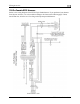
Wiring Overview WIRING SYSTEM OVERVIEW The following block diagram depicts the basic layout of the EFIS DB25 electrical connections and is for reference only. Read the specific instructions for each connection prior to installation. The colors shown refer to the Dynon-supplied EFIS harness.
3. INSTRUMENT INSTALLATION This section provides you with the information needed to physically and electrically install the EFIS-D6. While the EFIS-D6 includes a built-in electronic compass, it is recommended to install and calibrate the included EDC-D10A Remote Compass Module. Selecting a Remote Compass Module Location Finding a good location for the EDC-D10A remote compass module is critical to an accurate EFIS-D6 heading display.
Instrument Installation D10A is aligned with the EFIS-D6 to better than 1 degree. • All mounting hardware needs to be made from non-ferrous material such as aluminum, plastic, or brass. Many stainless steel screws are magnetic. If the item is attracted to a magnet, it should not be used in the installation. The EDC-D10A needs to be mounted in a location as free from magnetic interference as possible.
Instrument Installation The metal shield around the EDC communication cable is connected to the short black/white wire from the DB25. Connect this wire to ground. Power Inputs The EFIS-D6 has two separate power inputs, located on the DB25 EFIS connector. Only Master Switch Power is required to operate the instrument. The other input provides redundancy. Below is a table that explains both power inputs and their purposes. Both inputs share a common ground signal, wired to pin 3 on the EFIS connector.
Instrument Installation PC CONNECTION FOR FIRMWARE UPDATES On the EFIS 25-pin wiring harness available from Dynon, there are three wires bundled together, terminating in a standard DB9-pin female connector. This cable is 6’ long and pre-assembled for connection to a PC-based laptop. Route this cable to a convenient location that can be accessed whenever you need to update your product’s firmware or checklists.
Instrument Installation Altitude Encoder Wiring The EFIS-D6 outputs its altitude measurements in one of four standard serial If your transponder requires parallel Gray outputs and is readable by many modern code input, and you wish to use the EFIS-D6 transponders. The EFIS-D6 will function as your altitude encoder, you will need to properly whether or not this altitude encoder purchase Dynon Avionics’ Encoder Serial-tofunctionality is used. To use the EFIS-D6‘s Parallel Converter.
Instrument Installation SERIAL ALTITUDE FORMATS There are four formats used by serial transponders. Choose the correct format for your transponder in the ALTENC menu, using the FRMAT button.
Instrument Installation Audio Alert Output The EFIS-D6 has an audio alert output for sounding AOA and altitude alarms through an intercom or audio panel. You must have the optional AOA Pitot Probe to use this functionality. DB25 pin# 18 Color Function Green EFIS Audio Alert Output Connect the alarm output from the EFIS-D6 to the outside terminal of a 10 kΩ variable resistor (not included). Ensure that audio outputs are connected similar to the following diagram.
Instrument Installation Panel Location and Mounting The diagram at right shows the outside dimensions of the front bezel of the EFISD6. Note that the instrument is about seven inches deep and the supplied harness extends three inches more. Use the dimensions (in inches) found on the diagram to plan for the space required by the instrument. Take the following considerations into account when selecting a mounting location for the EFIS-D6.
Instrument Installation Installation of the EFIS-D6 main unit should only be completed once all other physical and electrical installations have been performed. This will ensure that last-minute adjustments will not have to be made with the EFIS-D6 mounted in the panel. The diagram above shows the dimensions expected for the proper installation of the EFIS-D6 into your panel using no mounting bracket. All units are in inches. Push the EFIS-D6 through the main panel hole.
Instrument Installation Connecting Static & Pitot Lines The AOA, pitot, and static ports on the back of the EFIS-D6 are equipped with 1/8” NPT Female fittings. To attach your pitot and static lines to the back of the EFIS-D6, you must use standard 1/8” NPT Male fittings at the end of each of the lines. The EFIS-D6’s attitude calculation requires either airspeed (from pitot and static) or GPS data. To ensure proper operation, at least one of these data sources must be available.
4. EFIS CALIBRATION AND CONFIGURATION During manufacture, your EFIS-D6 underwent a comprehensive calibration, verification, and burn-in routine that minimizes setup time and ensures that your EFIS-D6 meets Dynon’s stringent performance specifications. To account for your individual preferences and your aircraft’s particular setup, there are a few simple calibration and configuration steps that you must complete before using your EFIS-D6.
EFIS Calibration and Configuration Obtaining Magnetic Inclination and Intensity 1. Browse to web page: www.dynonavionics.com/docs/maginfo.html. (Looking up this information does not have to be done on a computer at the plane, with live Internet access.) 2.
EFIS Calibration and Configuration EDC-D10A HEADING CALIBRATION (ON GROUND ONLY) The procedure for in-plane calibration of the EDC-D10A involves pointing the aircraft in four directions and taking data at each direction using the EFIS-D6. The EFIS-D6 will then perform some calculations to ensure an accurate calibration. During magnetic calibration, do not turn the power off on the EFIS-D6. This will cause any recorded compass calibration data to be lost; the calibration will need to be restarted.
EFIS Calibration and Configuration 12. Wait for the message CALIBRATION COMPLETE before attempting to use the EFISD6 or remove power. Press BACK to leave the menu. This completes the EDC-D10A calibration process. The process can be repeated as often as desired.
EFIS Calibration and Configuration During magnetic calibration, do not turn the power off on the EFIS-D6. This will cause any recorded compass calibration data to be lost; the calibration will need to be restarted. 1. Enter the EFIS calibration menu by pressing any button beneath an EFIS page, then SETUP > MAGCAL. You should see a menu that reads GNDNRT, AIRRGT, and AIRLFT.
EFIS Calibration and Configuration decide if the performance is acceptable to you. If the resultant compass accuracy is not acceptable, you can either repeat the calibration process attempting to fly the maneuvers more smoothly, or install and calibrate the Dynon Avionics EDC-D10A Remote Compass. You will need to repeat this process anytime you move the EFIS-D6 to a new location in your plane or change the magnetic or electrical characteristics of the nearby environment (i.e.
EFIS Calibration and Configuration Configure Airspeed Color Thresholds To configure the airspeed bar color thresholds for your unit enter the EFIS > SETUP > IASCLR menu. This displays the Airpseed Color Threshold menu. In this menu, enter the values for five airspeed constants (Vso, Vs1, Vfe, Vno, and Vne), each of which has its own button.
5. APPENDIX The appendices contain additional information pertaining to the installation and maintenance of the EFIS-D6. You will find here a table of weights, specifications, a configuration table, the maintenance manual, the OAT Installation and Operating Guide, the AOA Pitot Installation Guide, and the Blind encoder Serial-to-Parallel Installation Guide.
Appendix 3. Ensure that the screen is at its full brightness level. To do this, enter the menu system by pressing any button and press DIM and increase the brightness until it will not increase anymore. 4. Let the unit remain on for 2 hours. 5. If, after these 2 hours, your EFIS-D6 has not turned off and does not display the INTERNAL BATTERY LOW warning, your battery passes the capacity test. 6. Make sure you recharge your battery; a full charge is reached when the voltmeter shows at least 16.
Appendix Alert Message Description ATTITUDE This alert is displayed anytime the RECOVERING… unit is rotated at a rate faster than 150 degrees/second or the unit is powered on with airspeed applied. Rotating the unit faster than this threshold will saturate the gyros, leading to potentially erroneous display. The blue/brown horizon indication will turn grey and black to indicate that the artificial horizon is not currently a trusted source.
Appendix Alert Message INTERNAL BATTERY LOW Description You will see this alert only when operating the unit solely off the internal backup battery. When its voltage has dropped below a certain threshold, you will see this alert. Additionally, the voltmeter will be displayed onscreen. When you see this alert, it is advisable that you turn the unit off by pressing the POWER button in Main Menu 1. REMOTE COMPASS NOT DETECTED The EFIS-D6 is unable to communicate with the EDC-D10A.
Appendix Problem Airspeed is inaccurate by between 1 and 10 knots (or equivalent, in other units) at takeoff speed. Solution You may recalibrate your EFIS-D6‘s zero pressure value. With your plane in as windless an environment as possible (e.g., a hangar), cover both the pitot and static ports with a sock or cloth to minimize airflow without putting pressure on the ports. Next, on the EFIS-D6, enter the EFIS main menu, press SETUP > SPDCAL.
Appendix We recommend that you also send your EDC-D10A remote compass along with your EFIS-D6. This ensures that if we upgrade the firmware in your EFIS-D6, the EDC-D10A will have corresponding firmware. While Dynon Avionics makes every effort to save and restore your unit’s settings and calibrations, we cannot guarantee that this will happen.
Appendix Appendix B: Dynon AOA/Pitot Installation and Calibration Thank you for your purchase of Dynon’s AOA/Pitot Probe. This guide walks you through the steps to install and calibrate both the heated and unheated versions of the AOA/Pitot Probe. While the probe senses standard pitot pressure, allowing it to work with any standard airspeed indicator, its AOA functionality is designed specifically to work with Dynon’s EFIS series of products. Do not expect it to work properly with another AOA system.
Appendix • Two plumbing lines (usually ¼” soft aluminum or plastic tubing) routed from the EFIS-D6 to the probe mounting location. • Adapters to interface with the 3/16” aluminum tubing from the probe to whatever plumbing lines are installed in the aircraft (AN919-2D for 3/16 to ¼ , AN819-4D sleeve AN818-4D nut, AN819-3D sleeve, and AN818-3D nut) • #36 Drill and 6-32 tap • AOA Pitot Mounting bracket.
Appendix instructions on the following pages. Read the specific instructions for each connection prior to installation.
Appendix Heater Controller Wiring Before making the connections to your Heated AOA/Pitot Probe and controller, refer to the Recommended Wiring Practices section on page 2-1. The chart at right provides general recommendations for wire gauge choice, given wiring run length.
Appendix controller. Remember that even when the controller is powered on, it only heats the probe the amount necessary to maintain temperature. The black wire should be permanently connected to ground. Cutting power to the heater controller should occur via the red power line, not the black ground line. Heater Status Connection Note: The probe heater functions properly whether or not you make this connection. It is simply a status output for your convenience.
Appendix these lines, you may drill all the way through the outer metal without affecting the probe’s waterproofing.
Appendix Boom mount PLUMBING NOTE: Because the pitot and AOA plumbing tubes have not been annealed, they work-harden rapidly when manipulated. Make gentle bends, and only bend any given section once. After mounting the probe, route the pitot and AOA lines from the probe to your EFIS-D6. The tube closest to the snout is the pitot line, while the tube in the rear is the AOA line. There is no static source on the probe.
Appendix flight regimes not listed that you suspect would create stalls at lower angle of attack it would be good to record those as well. • • • • With full power, no flaps With no power, no flaps With full power, full flaps With no power, full flaps Push the STALL button before performing each stall. When you push the STALL button, a 45second timer starts. Notice the “T” next to the time that is counting down.
Appendix Appendix C: Encoder Serial-to-Gray Code Converter Installation INTRODUCTION AND DESCRIPTION The Encoder Converter is an electronic device that receives the serial encoder data from the EFIS-D6 and outputs standard Mode-C parallel Gray code into your Mode-C transponder. This Encoder Converter requires data from the EFIS-D6 and is not to be confused with other standalone encoders available on the market. While the installation is not complex, it is important that you install the unit correctly.
Appendix directly to your switched avionics power. Ensure that all avionics power is off before performing the wiring step of this installation. If your Altitude Transponder has either a strobe signal or a D4 pin, leave these pins unconnected.
Appendix EFIS DB25 Pin# 13 21 Dynon EFIS harness color Blue/White (may be black on some harnesses) White Encoder Converter Wire Color Function Green (May be Red on older models) Serial Encoder Transmit Black Serial Encoder Ground STEP 3: EFIS-D6 ENCODER FORMAT For proper communication the EFIS Altitude Encoder format must be set to format number one. To change this setting, from the main menu, select: SETUP > ALTENC. Press FRMAT until it reads “1.
Appendix Appendix D: Replacing the EFIS-D6 battery pack 1. Remove the three 7/64” hex screws from the battery door of the EFIS-D6. Do not remove the Phillips or D-sub screws. Screw 1 Screw 3 Screw 2 2. If you previously had a battery, disconnect it from the EFIS-D6 by unplugging the battery connector and gently pulling out old battery. It is safe to gently pull on the battery wire to remove the battery. 3. Insert the battery with the “bumpy” side up, toward the foam. 4.
Appendix Appendix E: Upgrading EFIS-D6 to EFIS-D10A The EFIS-D6 is Dynon’s simple, more affordable version of Dynon’s full-featured EFIS-D10A.
Appendix Appendix F: Weights Adding any new instrument to an aircraft requires the installer to be aware of its weight and how that affects the overall weight and balance of the plane. The following are the weights of the EFIS-D6 and associated Dynon-supplied sensors. EFIS-D6 .............................................................................................................1 lb 9 oz (0.709 kg) EFIS-D6 + battery.......................................................................................