
Installation Guide Owner manual


Appendix
EFIS-D10A Installation Guide 7-11
Pinouts and Function Description
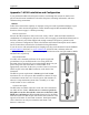
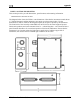
Below are the pinouts and function descriptions for the HS34’s male and female connectors. At a
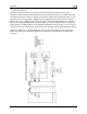
mini n in the Universal Connections diagram. All mum, you must make the connections show
other wiring connections depend on the external equipment you are connecting to the HS34.
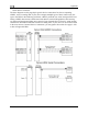
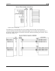
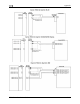
Many common radio and GPS connections are depicted in the Common Device Connections
section below. Note that the pin numbers are labeled on the face of both the female and male
connector.
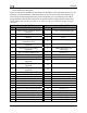
Male (on HS34) DB25 Female (on HS34) DB25
Pin# Function Pin# Function
1
Serial 1 RX (PC updates & second
serial port)
1
CDI + when deflected right
2 Serial 2 RX (SL30, GPS, etc) 2 VOR + when TO flag shown
3 DSAB A 3 LOC +
4
M
max V)
aster Power (10-30V, 250 mA
imum at 12
4
GS + when up UP
5
GP Output 1 (not currently
supported)
5
GS + when FLAG shown
6
GP Output 2 (not currently
supported)
6
DME Analog IN (0-8V,
40mv/NM)
7 G P 1 in (same as EMS GP in) 7 Resolver G
8 GP 2 in ( S GP in) same as EM 8 Resolver D
9 +5V out 9 Resolver F
10
GP 6 in (+15V GP in, not currently
supported)
ARINC 429 RX 2 B
10
11
GP 5 in (+15V GP in, not currently
supported)
11
ARINC 429 RX 1 B
12
GP 4 in (+15V GP in, not currently
supported )
12
ARINC 429 TX B
13 GP 3 in (same as EMS GP in) 13 ARINC 429 TX B
14 Serial 1 TX 14 CDI + when Left
15 Serial 2 TX 15 VOR own + when From flag sh
16 DSAB B 16 LOC -
17 Master Ground 17 GS + when Down
18 Contact in contacts) GS + when Flag hidden 4 ( Ssame as EM 18
19 Contact in contacts) 3 (same as EMS 19 Resolver C
20 Contact in 2 (same as EMS contacts) 20 Resolver H
21 Contact in 1 (same as EMS contacts) 21 Resolver E
22 Marker Outer Input 22 ARINC 429 RX 2 A
23 Marker Middle Input 23 ARINC 429 RX 1 A
24 Marker Inner Input 24 ARINC 429 TX A
25 Voice audio output (8V peak-peak) 25 ARINC 429 TX A