
Installation Guide Owner manual

Wiring Overview
EFIS-D10A Installation Guide 2-3
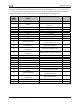
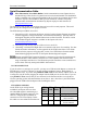
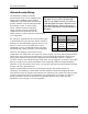
The pin assignments for the female 25-pin harness are repeated below. Note that the pin numbers
are labeled on the face of both the female and male connector. Each connection on the harness
supplied by Dynon is color-coded. These colors are listed in the following chart.
Female
DB25
Pin #
Dynon Harness Wire
Color
Function Details
1 Red Master Power (10-30 volts) Page 3-3
2 Yellow
Keep Alive Power (10-30 volts,
always on)
Page 3-3
3 Black Master Ground Page 3-3
4 Green DSAB-A Page 3-11
5 Blue DSAB-B Page 3-11
6 N/A No Connect
7 N/A No Connect
8 N/A No Connect
9 Black (bundled) PC Serial Ground Page 3-4
10 Orange (bundled)
EFIS-D10A Transmit / PC Serial
Receive (RS-232)
Page 3-4
11
White/Orange (Red on some
harnesses)
EDC-D10A Data B
Page 3-1
12
White/Blue (Black on some
harnesses)
EDC-D10A Power (12V)
Page 3-1
13
Blue/White (black on some
harnesses)
Serial Encoder Transmit (RS-232)
Page 7-32
14 N/A No Connect
15 N/A External Backup Power Page 3-3
16 Black Ground
17 N/A No Connect
18 Green Audio out Page 3-10
19 N/A No Connect
20 N/A No Connect
21
White (Bundled in Encoder
cable)
Serial Encoder Ground
Page 7-32
22 Yellow (Bundled)
EFIS-D10A Receive / PC Serial
Transmit (RS-232)
Page 3-4
23
White/Green (Green on some
harnesses)
EDC-D10A Data A
Page 3-1
24 White EDC-D10A GND Page 3-1
25 N/A No Connect