
Installation Guide Owner manual

Appendix
7-32 EFIS-D10A Installation Guide
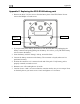
Appendix E: Encoder Serial-to-Gray Code Converter Installation
IN O PTION
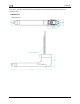
The Encoder Converter is an electronic device that receives the serial encoder data from the
EFI D to your Mode-C transponder.
This Encoder Converter requires data from the EFIS-D10A and is not to be confused with other
ay be
ith Gray code transponder
TALLATION
e
amage to your
RACTICES
chniques for all electrical connections, taking care to properly
ort circuit between any of the wires may cause damage to the
d to
.
he
lor
end of
output, the E
ncoder Converter. If your transponder does not
include this switched power output, the Encoder Converter power connections should be made
TR DUCTION AND DESCRI
S- 10A and outputs standard Mode-C parallel Gray code in
standalone encoders available on the market. While the installation is not complex, it is
important that you install the unit correctly. The Encoder Converter does not output an encoder
strobe signal.
The Encoder Converter is designed to be powered off voltages between 10 and 30 volts.
TOOLS AND EQUIPMENT
The following parts are not included with your Encoder Converter purchase but m
necessary to complete the installation.
Wire cutters
Connector crimp tool
Crimp pins
25-pin EFIS harness to mate with EFIS-D10A (may have been purchased with your
EFIS-D10A)
Connector to mate w
ELECTRICAL INS
The following section describes the wiring requirements for using the Encoder Converter. Pleas
follow these instructions explicitly as improper wiring can result in permanent d
unit.
RECOMMENDED WIRING P
NOTE: Use correct splicing te
insulate any exposed wire. A sh
Encoder.
The wire used in construction of your Encoder Converter is 22 gauge avionics grade Tefzel wire,
which meets Mil Standard MIL-W-22759/16.
Installing: Make sure all connections are secure and all wires are routed and strain relieve
ensure that the wires will not chafe against any other object in the aircraft.
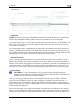
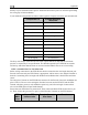
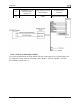
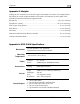
STEP 1: TRANSPONDER WIRING
Wire the Encoder Converter signals to their respective connections on your Mode-C transponder
Mode-C transponder pin-outs vary from device to device. To find the correct pin-out, look at t
manual for your transponder or contact its manufacturer. The table below details which co
wire should be connected to each Transponder pin. All of the wires listed in the table leave one
the Encoder Converter in a single bundle. If your transponder has a switched power
connect this to the power inputs on