EFIS-D10A Electronic Flight Information System Pilot’s User Guide P/N 100349-000, Revision K For use with firmware version 5.4 August, 2010 Dynon Avionics, Inc.
Contact Information Dynon Avionics, Inc. 19825 141st Place NE Woodinville, WA 98072 Phone: (425) 402-0433 - 7:00 AM – 5:00 PM (Pacific Time) Monday - Friday Fax: (425) 984-1751 Dynon Avionics offers online sales, extensive support, and continually-updated information on its products via its Internet sites: www.dynonavionics.com –Dynon Avionics primary web site; including: docs.dynonavionics.com – Current and archival documentation. downloads.dynonavionics.com – Software downloads. support.
Introduction Information in this document is subject to change without notice. Dynon Avionics reserves the right to change or improve its products and to make changes in the content without obligation to notify any person or organization of such changes. Visit the Dynon Avionics website (www.dynonavionics.com) for updates and supplemental information concerning the use and operation of this and other Dynon Avionics products.
Table of Contents Contact Information..............................................................................................................................................................ii Copyright..............................................................................................................................................................................ii Limited Warranty ...............................................................................................................
Table of Contents Menu Pages......................................................................................................................................................................4-11 5. EFIS Operation 5-1 POWER – Power on/off ................................................................................................................................................... 5-1 BARO – Changing Altimeter Setting .................................................................................
Introduction EFIS Autopilot Control .....................................................................................................................................................7-9 AP74 Autopilot Control...................................................................................................................................................7-11 Disengage/Control Wheel Steering (CWS) Pushbutton ..................................................................................................
1. INTRODUCTION Thank you for purchasing the Dynon Avionics EFIS-D10A. This section provides some important cautionary information and general usage instructions for this manual. Before You Fly We strongly recommended that you read this entire guide before attempting to use the EFIS-D10A in an actual flying situation. Additionally, we encourage you to spend time on the ground familiarizing yourself with the operation of the product.
Introduction Warning Dynon Avionics’ products incorporate a variety of precise, calibrated electronics. Except for replacing the optional internal backup battery in EFIS-based products per the installation guide, our products do not contain any field/userserviceable parts. Units that have been found to have been taken apart may not be eligible for repair under warranty.
Introduction The following icons are used in this guide: Any text following this icon describes functionality available only with the HS34 HSI Expansion Module connected to your system. Any text following this icon describes functionality available only with the AP74 Autopilot Interface Module connected to your system. Any text following this icon describes functionality that is possible when multiple Dynon Avionics products are networked together via the Dynon Smart Avionics Bus (DSAB).
2. PRODUCT OVERVIEW This section provides a general overview of the various parts of the EFIS-D10A as well as a theory of operation. The information in this section serves as a reference only and helps familiarize you with the inner workings of the unit. It should not be used for diagnostic or reparative work. EFIS-D10A Hardware The EFIS-D10A uses solid-state sensors to provide accurate and reliable information about your flying environment in an easy-to-use interface.
Product Overview SENSORS AND INPUTS Attitude information is obtained from 3 solid-state gyrometers, 3 solid-state accelerometers, and the airspeed pressure sensor. Heading information is obtained from 3 solid-state magnetometers housed in the EDC-D10A (internal compass sensors are also available on the EFIS-D10A only). Airspeed, altitude and angle of attack are obtained from three separate pressure transducers.
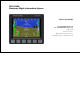
Product Overview DISPLAY The display is a 4-inch, 320 by 240 pixel, 450-nit LCD screen. BUTTONS AND KNOBS User interaction takes place via the six buttons along the bottom of the front panel of the unit. When an AP74 Autopilot Interface Module is configured to control the EFIS-D10A, its VALUE knob changes values when in various EFIS menus. When no menus are displayed the AP74 can adjust the barometer, altitude bug, and heading bug.
Product Overview Ball Altitude Airspeed AOA Turn Rate Heading Attitude GPS Pitot Static X* X* X* X X X X X* X X X X X X AOA Magnetometers Rate Sensors Accelerometers X X X X X X X X X ATTITUDE CALCULATION The EFIS-D10A artificial horizon display (attitude) is generated via a complex algorithm using a multitude of sensors. Your EFIS attitude is not reliant on any single external system.
Product Overview the EFIS-D10A’s attitude. COMPASS ACCURACY AND AUTOPILOT PERFORMANCE If you are using your EFIS-D10A to control Dynon’s Autopilot, it is critical that the magnetic heading be as accurate as possible for comfortable operation in HDG mode and radio-based VOR/NAV mode. The aircraft’s compass must be installed correctly, calibrated, and operating well in all attitudes.
3. PRODUCT OPERATION After reading this section, you will be familiar with the basics of how to use your EFIS-D10A. For details regarding specific procedures (e.g., adjusting display brightness, changing the altimeter setting, setting the clock, etc.) please refer to the EFIS Operation section. Front Panel Layout All normal operation of the EFIS-D10A happens via the front panel. The front panel contains buttons and a display. Buttons – There are six buttons on the front panel of the EFISD10A.
Product Operation Display The EFIS-D10A display is the most obvious and commonly used output of the device. It is capable of displaying EFIS, HSI, and/or engine data simultaneously. SCREENS AND PAGES The terms in the following bulleted list are used in this section and are defined as follows: Screen/Screen Configuration – Screens consist of one or two pages from the EFIS-D10A or from another DSAB-connected Dynon Avionics product.
Product Operation The EFIS-D10A has several pre-defined screen configurations. The basic layout of a screen configuration is represented by one of two icons on D10-series product. The table at right shows the two icons and their meaning. The predefined screen configurations with their respective icons are as follows: Icon Left Page Area Right Page Area 1/2 1/2 One page that occupies all of the screen area The SCREEN LIST Menu uses icons to illustrate the layout for each screen configuration.
Product Operation CYCLING BETWEEN SCREENS There are two methods for cycling between pre-defined screens: via the menu and via hotkeys. Screen Cycling Using the SCREEN LIST Hold for two seconds Navigate to the SCREEN LIST menu by holding button six for at least two seconds when no menu is present (see the figure to the right). Note that if you only press button six momentarily, the display cycles to the next screen in your screen rotation. Use the DOWN▼/UP▲ buttons to move the caret (>).
Product Operation Changing the Screen Rotation You may use the out-of-the-box screen rotation or define your own. If you desire to use the initial rotation, no user configuration is required. If you desire to use a custom cycling order, then user configuration is necessary. To configure a custom rotation, navigate to the SCREEN LIST menu page by pressing button six for approximately two seconds when no menu is present.
Menus All interaction with the EFIS-D10A is accomplished through the use of its menu system. The menu system is accessed and navigated via the six buttons located on the front of the unit. PAGE-SENSITIVE MENUS On a screen where no menu is already present, buttons two through five are used to display a menu. With no menu displayed, pressing any one of these buttons causes the menu for the page above it to show at the bottom of the screen.
If a menu contains more options than there are buttons, the MORE label is displayed over button five. Pressing this button shows you the next set of options in the current menu. In any menu, press the BACK button to return to the previous menu and save any changes. In all top-level menus, button six is the EXIT button. Pressing EXIT removes the menu system and moves many of the onscreen elements down to their original positions.
Product Operation and EXIT. Pressing HDG, IAS, or ALT allows the user to configure heading, indicated airspeed, or altitude bugs, respectively. To exit the menu system, press the BACK button as many times as is needed to reach an EXIT button. This varies based upon how deep you are into the menu system. DESCRIPTIONS IN THIS GUIDE Throughout this guide, the “>” character is used to indicate entering a deeper level of the menu system.
4. AVAILABLE PAGES The EFIS main pages use various tapes, digital displays, and other indicators overlaid on an artificial horizon. On the 2/3 and full-screen pages, you may also display up to two “info items” on the left and right side of the main page. HSI pages use text and a DG style compass by itself or overlaid with lines and arrows of different colors. Note: HSI pages use data that is obtained from a source external to the EFIS-D10A.
Available Pages EFIS Main pages Available in full-page format The EFIS-D10A default screen rotation includes only 2/3 EFIS pages combined with the various EMS and HSI pages described below. However, you may also choose screen configurations that use 1/3 and full-screen pages. The 2/3 and full-screen pages can display EFIS- and EMS-related info items on the left and right side of the screen.
Available Pages Horizon line, pitch and roll indicators Bounded on the top by blue, and on the bottom by brown, the horizon line behaves in much the same way as a traditional gyro-based artificial horizon. Unlike a mechanical artificial horizon, the EFIS-D10A’s horizon has no roll or pitch limitation. The horizon line stays parallel to the Earth’s horizon line regardless of attitude.
Available Pages On the EFIS page, these two items are enabled via the EFIS > SETUP > CLUTTR menu under a single item, which can be set to either CDI:N, CDI:Y, or CDI+GS. The CDI is located just above the slip/skid ball when displayed, and behaves much as described in the HSI Operation section on page 6-1. The CDI needle is green when sourced from a NAV radio and magenta when sourced from GPS. When to/from information is available, the center of the CDI is an arrow; when on an ILS, it is a filled-in square.
Available Pages Like a conventional gyro-stabilized magnetic compass, magnetic heading reacts immediately to turn rate so that heading changes are reflected immediately. It then uses magnetometer data over the long term to ensure that it remains correct. Additionally, heading is corrected for attitude so that it is accurate as you pitch and roll.
Available Pages 4000 ft/min, the VSI bar is scaled to indicate a 6-second trend only up to 1000 ft/min. When set to display 1000 ft/min, the VSI bar is scaled to indicate a 12-second trend up to 500 ft/min. During the first 30 seconds of operation, the altitude tape and digital readout are not displayed as the unit needs a small amount of time before altitude measurements are deemed accurate.
Available Pages pointing arrows are left. Depending on your installation and configuration, an audible alarm may also occur when near or in the stall. This audio alarm is accompanied by a flashing red triangle at the top of the AOA display. To judge when a stall will occur, remember that the AOA indicator is showing actual AOA, and the stall AOA changes with configuration.
Available Pages Bugs Bugs may be set to mark a desired heading, airspeed, or altitude. These bugs are represented by a yellow inverted arrow located at the desired value on the tape. If the set heading, altitude, or airspeed is currently off-screen, the bug icon appears at the edge of the moving tape closest to the desired value. Your airspeed, heading, or altitude is at its set bug value when the bug’s inverted triangle encloses the triangle of the digital readout’s pointer.
Available Pages clock indicates whether the unit is displaying Local time (L), Zulu time (Z), or a timer (T). If a GPS is connected to your Dynon network and is outputting time information, the Zulu time of all connected products is auto-set to that reported by the GPS. Autopilot Status Indicator When a Dynon Autopilot is installed and configured, an AP Status Indicator is displayed at the bottom left of the EFIS page.
Available Pages Times/Auxiliary Page Available in 1/2 | 1/2 format This page displays times information on the left half of the screen and – if a Dynon EMS-based product is connected per the EFIS-D10A Installation Guide – user-customizable auxiliary information on the right half of the screen. For information about the auxiliary information half of the page and engine-related timers, please see your EMS-based product’s Pilot’s User Guide. The times half is divided into two sections: TIME, and TIMERS.
Available Pages Menu Pages Available in full format Some setup menus require a full page to display all the available options. Menu Pages use a caret symbol (“>”) to indicate the currently selected line. Use the DOWN▼ and UP▲ buttons to scroll through the list of options. Any line on a Menu Page that is followed by ► has more options to configure inside of it. Press SEL► to expand the menu into another list of options to the right.
5. EFIS OPERATION This section guides you through each of the EFIS main page menu selections and their sub-menus. To enter the EFIS menu system, press any button (except for buttons 1 and 6) directly beneath an EFIS main page. If no EFIS main page is displayed, you must switch to a screen configuration that includes and EFIS main page as described on page 3-4.
EFIS Operation The BARO setting can be changed using the HS34’s VALUE knob, depending on the configuration settings in EFIS > SETUP > HSI > VALUE KNOB. The BARO setting can be changed using the AP74’s VALUE knob, depending on the configuration settings in EFIS > SETUP > AP > VALUE KNOB. The current indicated altitude is preserved across a power cycle. When powered down, the instrument saves the indicated altitude.
EFIS Operation In the HDG/TRK bug menu the value-setting box is displayed in the lower part of the display. Press SEL► to select which digit to change and DEC- and INC+ to change the selected digit. Press the SYNC button to synchronize the heading/track bug to your current heading or track. As you increment or decrement the bug value it rolls over at 360 degrees, returning the value to 001. If you have the heading or track bug displayed, the marker moves left or right along the tape as you change its value.
The airspeed bug can be adjusted on any EFIS page in the system and is synchronized across all EFIS-based units. When in the BUGS > IAS menu, rotate the AP74’s or HS34’s VALUE knob to quickly change the bug’s set value. ALTITUDE In the BUGS menu, press ALT. Press the TOGGLE button to turn on or off the altitude bug display on the altitude tape. In the ALT bug menu the value-setting box is displayed in the lower part of the display.
EFIS Operation when passing through 500 feet from the target altitude. The target altitude is considered captured when altitude is within 150 feet of the target. Flying more than 200 feet away from the target triggers a short audio alert and alternates the bug in red and yellow as a visual alert. When below the 200-foot window, a rising tone is sounded; when above the 200-foot window, a descending tone is sounded. The visual climb or descend alert clears after recapturing the target altitude or 30 seconds.
EFIS Operation To load checklists and data panels onto your EFIS-D10A, you must upload them as described in the Dynon Product Support Program help file. Pushing the LIST button displays the 5 main categories as set up in the Dynon Support Program. Press a button corresponding to the desired category to show the checklists and data panels beneath it. When you display a checklist, it takes up the entire screen. See the Dynon Support Program for more detailed information on entering checklists and data panels.
EFIS Operation time is usually an offset in hours from Zulu time, set the minutes value in the Zulu time portion of the box; notice that the local time minutes setting change at the same time. Then, set the hours for local and Zulu times independently. Once you have set Zulu time, you should never need to change it, as it is independent of daylight saving time. When connected to a GPS which is outputting time information, Zulu time is synchronized to the GPS and cannot be set on the EFISD10A.
EFIS Operation SHOW/HIDE DISPLAY ITEMS In the EFIS > SETUP > CLUTTR menu, you can turn on or off almost every item displayed on the EFIS page. As with all other menu items, these options are abbreviated to commands containing 6 letters or fewer. Pressing a button corresponding to one of these options turns the respective onscreen item on or off. The following table summarizes the display item abbreviations and their function.
EFIS Operation Abbreviation ROLL Display Item Roll Scale GTRK Ground Track WIND Winds Aloft ASTRND VSI Airspeed Trend Vertical Speed Indicator EFIS-D10A Pilot’s User Guide Function Toggles and configures the display of the roll scale. When set to “N”, the roll scale is not displayed. When set to “1,” the roll scale stays fixed on the screen and the pointer moves along the scale, like a jet EFIS presentation.
EFIS Operation Abbreviation CDI Display Item Course Deviation Indicator CRS Course Pointer TRIM Elevator Trim Function Toggles and configures the display of the CDI and glideslope. Choosing “CDI” causes the course deviation indicator to display above the slip/skid ball. Choosing “CDI+GS” causes both the CDI and glideslope indicators to display, with the glideslope indicator displayed next to the roll scale.
EFIS Operation INFO – Informational Items In the EFIS > INFO menu, you have the option of displaying an informational display item on either the left or right side, or both. You may display a voltmeter (VMETER), g-meter (GMETER), vertical speed indicator (VSI), OAT/true airspeed/ density altitude (OAT), and engine RPM/MAP info (ENGINE). More detail about each of these is given below. Voltmeter The voltmeter displays 3 rows of information corresponding to the three power inputs on the EFISD10A.
EFIS Operation is the maximum positive g-force experienced by the EFIS-D10A since reset. The middle row, labeled CR, is the current g-force experienced by the EFIS-D10A. The bottom row, labeled MN, is the minimum g-force experienced by the EFISD10A since reset. To reset the max and min g-force values to the current g-force value, enter the EFIS > INFO menu and press the RSET G button.
EFIS Operation This change is only used if the primary OAT (or entire DSAB network) fails and the EFIS switches to the locally connected OAT. ENGINE (Manifold Pressure and RPM) The engine informational item allows you to display engine manifold pressure and RPM on the EFIS page. This requires that the manifold pressure sensor and tachometer pickoff are properly installed and configured on a DSAB-connected EMS-based product.
EFIS Operation without auto-dim. The system records the new set level as the desired brightness, and auto-adjusts around the new set point. TIMER – Setting and using a timer Enter the EFIS > TIMER menu. In the value setting box, the DOWN or UP label is displayed, depending on which timer type is currently selected. The currently running timer is displayed on the Times/Aux Page, as described on page 4-10. Use the following points as you work with the timer.
EFIS Operation OATSET – Setting Temperature Offset If you did not purchase an EFIS or EMS outside air temperature sensor from Dynon Avionics, you may still manually adjust the OAT to an approximate value. With this manually entered information, the EFIS-D10A calculates and displays true airspeed (TAS) and density altitude as it does when an OAT is connected. Ensure that you have indicated that an EFIS OAT is not installed; enter the EFIS > SETUP > OAT menu and press INSTALLED until the value is “N.
EFIS Operation when you marked the record. For information about retrieving data and reading the file produced, please see the help file included in the Dynon Product Support Program (version 5.0 and higher). The EFIS-D10A has a limited amount non-volatile internal storage for the data log.
6. HSI OPERATION This chapter explains how to use the EFIS-D10A’s HSI functionality. Required Connections To display an HSI on the screen, an external receiver is needed. The currently supported data sources are a Garmin SL30 Nav/Comm radio via a serial connection (Nav data), a Garmin GNS-430/530 GPS/Nav/Comm (GPS data), or any GPS that outputs in either NMEA-0183 or aviation format. Please refer to the EFIS-D10A Installation Guide for instructions on how to connect these devices to your Dynon network.
HSI Operation Accessing the HSI/DG Page The HSI is displayed as a full-screen page on your EFIS-D10A. If the HSI is defined as part of a screen setup in your rotation, display the HSI page using either of the screen rotation hotkeys (buttons 1 and 6) until the appropriate page is displayed. If the HSI screen is not in your rotation, you can access the HSI by holding down the right button and navigating to the HSI screen. See page 3-2 for more information on screen configuration.
b. "NAV" in black letters on a green background. This indicates that the system is in NAV mode, but there is no active VOR or localizer tuned. This is the same as a cross hatch indicator in the TO/FROM flag on a mechanical CDI. Do not rely on any indications on this page except for the DG and TAS when this flag is set. c. "VOR" in green text. This means the radio is tuned to a standard VOR station and is giving a valid TO or FROM indication. d. "LOC" in green text.
HSI Operation 4. Bug indicator. This user-settable bug also appears on the EFIS heading tape. Colored yellow, it can be toggled on and off using the HSI menu or the main EFIS menu. The HEADING knob on the HS34 always controls the heading bug. Turning the knob when the bug is not displayed switches the bug to the on state. Press the HEADING knob to sync the bug to the current heading. 6-4 5. True Airspeed Indicator. If it is possible to calculate true airspeed on the device then it is displayed here.
HSI Operation Navigation Radio Overlay The figure at right shows an HSI page with information sourced from a navigation radio. This data could be a VOR or a localizer. The various elements are described below. 1. Text displays. The text displays (located along the left side of the HSI Page) provide a variety of information.
HSI Operation HS34’s knob must be used to set the OBS; the SL30’s OBS is overridden by the course information sent out by the HS34. 6-6 3. Course Deviation Indicator (CDI). When tuned to a VOR, the CDI indicates how far to the left or right of your selected radial you are. Full scale deviation indicates ten degrees of deviation from the radial that has been chosen as the course. When tuned to a localizer, full scale represents 2.5 degrees of deviation.
HSI Operation another. The primary bearing indicator is depicted by a yellow diamond and the standby indicator is depicted by an orange circle. These elements only appear when the active and/or standby VORs are tuned to an active frequency. A numerical display of your primary (labeled NAV) and standby (labeled SBY) bearings and a reminder of which symbol represents each bearing is in the text area of the page. The HS34 adds the possibility of having many more bearing sources in the system.
HSI Operation as "CRS." In a situation with no winds, keeping the course indicator pointed straight up and in line with the heading pointer keeps the aircraft on course. This indicator is fixed to the rotation of the DG, so it is easy to see which way you must turn to get on course. The course indicator is only present when you have an active flight plan in your GPS and are navigating to a point. *Some GPS units do not report course direction.
HSI Operation flying directly on course, your BTW and course lines overlap one another. The text area of the page contains a numerical display of this bearing and a diamond icon to signify its symbol on the display. The HS34 adds the possibility of having many more bearing sources in the system, so the behavior of the BRG SRC button is dependent on how many devices you have connected. When you press this button, if you have only one possible bearing source, the bearing source toggles on and off.
HSI Operation ground track, keeping this directly above your course pointer (when the CDI is centered) keeps you on course, even if your magnetic heading is different. As long as a valid GPS source is detected by the system, the ground track indicator can be displayed. This is not dependent on the currently set NAV source. HSI Menu Structure NAVSRC - This is used to choose what navigation source is displayed on the HSI page and the EFIS main page.
HSI Operation external course command to control the instrument, this course adjustment also works. If the GPS or NAV device is in a mode where it is ignoring course commands, turning the course knob results in no change on the screen. This is true when you are in most GPS modes. SCALE (GPS mode) - This is used to cycle through the three GPS scale modes. The scale button only exists if the source you are connected to is not providing scale information.
7. AUTOPILOT OPERATION This section guides you through the indicators and operation of Dynon’s EFIS-based Autopilot (AP) system. This section assumes that the AP has already been installed, configured, and tuned according to the EFIS-D10A Installation Guide. Additionally, it assumes that you are already familiar with the operation of the EFIS-D10A menu system, documented throughout this guide.
Autopilot Operation normal business hours, the Forum is a convenient way to interact with Dynon Avionics Technical Support. The Forum also allows online sharing of wiring diagrams, photos, and other types of electronic files. All Dynon instruments connected via DSAB must be running the same firmware version. This applies to the servos and AP74 as well, which are updated via the Bus Master EFIS.
Autopilot Operation Additionally, an Autopilot status indicator is always displayed at the lower left side of the EFIS page, as shown at right. In a 2-axis system, the left indicator displays the state of the roll servo, and the right indicator displays the state of the pitch servo. If only a pitch or only a roll servo is installed, that axis’ indicator is shown just to the right of the “AP:” display. When either the roll or pitch axis is engaged, the entire indicator has a black background.
Autopilot Operation AP Status Indicator Modes AP State Roll Display Pitch Display Status: Altitude Hold Mode; AP uses Altitude Bug as target altitude N/A ALT Warning: Servo slipping Mode display with yellow background Mode display with yellow background AP Status Indicator Errors AP State Warning: Servo has been calibrated but not tested (See: SETUP > AP > SERVO TEST) Warning: Airspeed outside min or max airspeed. See: SETUP > AP > PITCH SERVO.
Autopilot Operation If, while flying in GPS NAV mode, the user cancels the active waypoint or the GPS sends malformed navigation data, the AP fails over to TRK mode. If, while flying in HDG mode and compass data is lost, the AP fails over to TRK mode (if valid GPS data is present). If, while flying in NAV or TRK mode and GPS data is lost, the AP fails over to HDG mode (if valid compass data is present).
Autopilot Operation the maximum bank angle, set in that menu. See the EFIS-D10A Installation Guide for detailed information on configuring these parameters. HDG: HEADING MODE – ROLL SERVO When the AP is engaged in Heading Mode, it uses the roll servo to control the aircraft’s magnetic heading, with the goal of following the heading bug. You may adjust the heading bug, causing the AP-controlled aircraft to turn toward the new target heading.
Autopilot Operation Mode, it takes its instruction from the GPS unit’s horizontal navigation information. The AP’s goal in the roll axis is to center the CDI, flying you to the active waypoint on the desired course. NAV: VOR NAVIGATION MODE – ROLL SERVO NAV/VOR mode is available whenever a NAV radio source is selected as the HSI page’s NAVSRC and the CDI reads TO or FROM. NAV/VOR mode is indicated by the annunciation “VOR” in the AP LAT:LON status.
Autopilot Operation ALT: ALTITUDE MODE – PITCH SERVO When the AP is engaged in Altitude Mode, it uses the pitch servo to control the aircraft’s aircraft’s altitude. You may adjust the altitude bug, causing the AP-controlled aircraft to climb or descend toward the new target altitude at the average vertical speed defined during setup. In Altitude Mode, the AP’s goal in the pitch axis is to align the triangle of the numeric altitude box with the inverted triangle of the altitude bug.
Autopilot Operation AP Control Methods The AP can be controlled and monitored in a number of ways (described in detail in the sections below): EFIS menus: Set HDG or TRK and ALT bugs (AP targets), change AP modes, engage/disengage AP AP74 AP Control Panel: Set HDG or TRK and ALT BUGS (AP targets), arm AP modes, engage/disengage AP HS34 HSI Control Panel: Set HDG or TRK and ALT BUGS (AP targets) Disengage/Control Wheel Steering (CWS) pushbutton: engage/disengage AP EFIS Autopilot Control This sect
Autopilot Operation (HDG, TRK, or NAV)OFF/ON: The menu label also reflects the currently active lateral mode, and whether or not the AP is engaged in that mode. Pushing this button toggles between ON and OFF, activating and deactivating the roll servo in the specified mode. ALT and HDG or TRK modes can be enabled independently of each other. When the Autopilot is engaged in HDG or TRK mode, the heading bug is synchronized to the current heading or ground track, respectively.
Autopilot Operation AP74 Autopilot Control This section describes how to control the Autopilot via the AP74. When an AP74 is installed, the Autopilot can still be controlled via the EFIS-based AP menu. The AP74 has all the functionality of the EFIS > AP menu, while providing a more efficient way to interpret and use the Autopilot. It also provides some additional features, such as the ability to arm modes prior to engagement, and easy adjustment of AP targets via its dedicated knob.
Autopilot Operation AP Button: When its indicator is off, pressing the AP button engages the AP in the pre-armed mode(s) indicated by the Horizontal and Altitude Mode button indicators below. Depending on how you have configured bug synchronization, the AP may synchronize the bugs for pre-armed HDG, TRK, or NAV modes upon pressing the AP button. Read Pre-select Configuration on page 7-14 for more details on configuring this behavior for your needs.
Autopilot Operation When its indicator is on, pressing the button disarms/deactivates the roll servo and turns off the button’s indicator. NAV Button: When its indicator is off, pressing the NAV button arms the roll servo in Navigation Mode and turns on the indicator. If the AP is already engaged, pressing the NAV button activates the roll servo in Navigation Mode. In Navigation Mode, the AP flies the aircraft based on the navigation information displayed on the HSI page.
Autopilot Operation FIRST ACTION mode. A second push of the VALUE knob within 5 seconds after rotating the knob de-activates the VALUE knob and closes the pop-up window. If there is no further action (either a knob push or knob rotation), the VALUE knob automatically de-activates (times out) after 5 seconds and closes the pop-up window.
Autopilot Operation NEVER: The HDG and ALT bugs are never automatically modified by turning on the AP or changing AP modes. Be aware that the bugs are highly likely to be set far away from the current heading and altitude at the time of AP engagement; this will result in the AP immediately commanding a turn and a climb or descent at time of engage. When using this mode, we recommend that you verify the EFIS’ bugs settings prior to EVERY Autopilot engage.
Autopilot Operation HOLD TO ENGAGE Setting HOLD TO ENGAGE to Y allows you to engage the Autopilot by holding the Disengage/CWS Button for more than 2 seconds. This allows for a convenient alternative to engaging the Autopilot via the menus and/or AP74 AP button. Default is N. When this mode is active, anytime the autopilot is disengaged you can engage it by pressing and holding the Disengage/CWS Button for more than 2 seconds, then releasing.
Autopilot Operation If CWS mode is engaged and during this time airspeed exceeds AIRSP MAX (SETUP > AP > PITCH SERVO) releasing the AP Disengage/CWS Button will not re-engage the AP. The Autopilot can only be re-engaged when airspeed is below AIRSP MAX. Optional Preflight Checklist If you desire an Autopilot preflight test, the following can be used as a baseline. 1. 2. 3. 4. With the circuit breaker for the servos powered OFF, test the controls for proper operation of the control surfaces.
8. ALERTS Alarm Indicators Any time a built-in or preconfigured alarm set point is exceeded, you are alerted to the fact via the alarm bar and menu at the bottom of the screen. When an alarm is triggered, the following things occur: A red alarm bar appears at the bottom of the screen with a message identifying the out of range measurement Below the alarm bar, the alarm menu gives you options for what to do next.
Alerts When configured for voice alerts, the HS34 reads out an alarm that occurs, such as “CHT 1 HIGH” or “LOW FUEL.” These voice alarms can be acknowledged and silenced just like the EMS tone. SHOW PAGE If the alarming measurement is not displayed on your current screen, or is available on a page which displays it better, a SHOW [PAGE] button is included in the alarm menu. [PAGE] is replaced with the name of the actual page that is displayed when you press the button.
Alerts Multiple Alarms Any time multiple alarms occur in quick succession, they are handled in the following way: 1. 2. 3. 4. 5. Each numeric value and gauge posts its alarm by turning red, blinking, bringing up the alarm bar, and triggering the external light and audio alert. Alarm messages in the alarm bar are stacked into memory and presented in the order in which they occurred, unless a higher priority alarm occurs. Removal of the Alarm Bar requires separate pilot acknowledgement of each alarm.
Alerts NETWORK CONNECTION LOST: This error means that all network communication has stopped. In this event, no instruments share data or settings until the cause of the communication problem is resolved and all units are power cycled. Individual units that are powered on and functioning continue to function using their internally-derived data.
9. APPENDIX This appendix contains information not covered in the main section of the manual. This section contains reference tools such as a detailed description of the serial data format output by the EFIS-D10A, a specifications sheet, and a troubleshooting guide. This section also contains details regarding EFIS-D10A servicing. Appendix A: Serial Data Output The EFIS-D10A has one RS232 serial port which outputs EFIS data.
Appendix EFIS SERIAL DATA OUTPUT The format for the data sent out the EFIS RS232 port is: Start Char 1 3 5 7 9 10 13 14 18 21 25 26 Width Description Notes 2 2 2 2 1 3 1 4 3 4 1 4 Hour Minute Second Fractions Pitch Sign Pitch Roll Sign Roll Yaw Airspeed Altitude Sign Altitude 30 1 31 3 Turn Rate/VSI Sign Turn Rate or VSI 34 35 1 2 00 to 23, current Zulu time hour according to EFIS-D10A’s internal clock. 00 to 59, current Zulu time minute according to EFIS-D10A’s internal clock.
Appendix Start Char 37 38 40 42 Width Description Notes 1 2 2 6 Vertical g’s Sign Vertical g’s Angle of Attack Status Bitmask 48 50 52 2 2 2 Internal use Checksum CR/LF ‘+’ or ‘-’ (positive means aircraft is experiencing upward vertical acceleration). 00 to 99, vertical g’s in units of 1/10 g (99 = 9.9 g’s). 00 to 99, percentage of stall angle. A 6-character ascii-hex field representing a 24-bit status bitmask.
Appendix Should you experience difficulty with your product that is not solved by reading the troubleshooting section or by posting on our forum, please call us at (425) 402-0433 or email us at support@dynonavionics.com. Be sure to have the EFIS-D10A’s firmware version number ready when you contact us. To locate your product’s firmware version, refer to the Check firmware version section on page 5-10. See the following list of alert messages displayed by the EFIS-D10A.
Appendix Alert Message ATTITUDE RECOVERING… TEMPERATURE UNSTABLE TEMPERATURE OUT OF SPEC Description This alert is displayed anytime the unit is rotated at a rate faster than 150 degrees/second or the unit is powered on with airspeed applied. Rotating the unit faster than this threshold will saturate the gyros, leading to potentially erroneous display. The blue/brown horizon indication will turn grey and black to indicate that the artificial horizon is not currently a trusted source.
Appendix Alert Message INTERNAL BATTERY LOW Description You will see this alert only when operating the unit solely off the internal backup battery. When its voltage has dropped below a certain threshold, you will see this alert. Additionally, the voltmeter will be displayed onscreen. When you see this alert, it is advisable that you turn the unit off by pressing the POWER button in Main Menu 1. REMOTE COMPASS NOT DETECTED The EFIS-D10A is unable to communicate with the EDC-D10A.
Appendix Alert Message OAT SENSOR NOT DETECTED Description This alert appears when the EFIS has an OAT connected and then loses that connection for some reason. Either the EDC-D10A has become disconnected, or the OAT sensor itself has become disconnected from the EDC-D10A. EFIS-D10A Pilot’s User Guide End condition Double-check your wiring between the EFISD10A and the EDC-D10A as well as that of the OAT sensor.
Appendix Appendix D: EFIS-D10A Specifications Mounting: Mechanical Operating Temperature Power Connections Screen 9-8 Weight: Fits into standard 3 1/8” panel hole Optional flush mount bracket available 1 lb. 9 oz. (700 g) 1 lb. 15 oz. (880 g) with internal battery AP74: 10.7 oz. HS34: 11.3 oz. -22° to 122° F (-30° to 50° C) Voltage: Power: 10 - 30 Vdc 8 watts typical; 13 watts maximum Wiring: D-25 male Type: Backlight: Size: Resolution: AMLCD, TFT (Thin Film Transistor) 450 nits 4.
Appendix Inputs/Outputs EFIS-D10A Pilot’s User Guide 1 - Audio Alarm 1 - RS-232 bidirectional PC communication 1 - RS-232 data input (GPS, SL30, etc.