EFIS-D10 Installation Guide *** It is the installer’s responsibility to ensure a correct installation. *** Revised: Thursday, September 11, 2003 Copyright 2003 by Dynon Avionics Inc.
EFIS-D10 Installation Manual 2003 Dynon Avionics Inc. All rights reserved. This Installation Guide and the information contained herein is the proprietary data of Dynon Avionics. No part of this manual may be reproduced, copied, transmitted, disseminated or stored in any storage medium, for any purpose without the express written permission of Dynon Avionics, Inc. Dynon Avionics, Inc.
EFIS-D10 Installation Manual TABLE OF CONTENTS Table of Contents .......................................................................................................................... 3 A Note from Dynon Avionics ....................................................................................................... 4 Introduction................................................................................................................................... 5 Description...............................
EFIS-D10 Installation Manual A NOTE FROM DYNON AVIONICS Congratulations on your purchase of the Dynon Avionics EFIS-D10. As you probably know, EFIS (Electronic Flight Information System) technology has made great advances over the past few years. Because of the many advances in the technology upon which an EFIS system is based, we are able to bring you extremely capable avionics at a surprisingly low price. The EFIS-D10 was designed to be both easy to install and to operate.
EFIS-D10 Installation Manual INTRODUCTION The information presented in this manual pertains to the physical mounting of the EFIS-D10 electronic flight information system, the optional EDC-D10 Electronic Digital Compass, and the optional Dynon Avionics Pitot tube. Because some of the components mentioned above are optional, and you may not have purchased all the components, you need only read through the relevant sections of this guide.
EFIS-D10 Installation Manual Required but not supplied • Wire cutters • Wire (22 AWG); see recommended wiring practices • Connector crimp tool • #2 Phillips screwdriver • Two 7/16 wrenches • Standard RS232 serial cable • DB-25 Female connector with crimp pins • D-9 Female connector with crimp pins for PC interface • (optional) D-9 Female connector with crimp pins for EDC-D10 remote mount compass.
EFIS-D10 Installation Manual ELECTRICAL INSTALLATION The following section describes the wiring requirements for using the EFIS-D10. Please follow these instructions explicitly as improper wiring can result in permanent damage to your unit. All electrical power and data lines interface with the EFIS-D10 via the 25-pin D-Sub connector on the back of the unit. You should ensure that all electrical connections are tested and properly working before completing the final physical assembly.
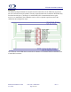
EFIS-D10 Installation Manual Schematic The following diagram details the external electrical connections for the EFIS-D10. In practice, not all of connections may be needed. The only required connections to make the EFIS-D10 fully functional are MS (pin 1), GND (pin 3) and the RS232 PC Communication harness (pins 9,10,22). As mentioned in the Calibration section, a PC is required to perform some of the calibration and configuration steps. The connector on the EFIS-D10 is a male D-25 connector.
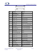
EFIS-D10 Installation Manual Figure 1 Rear view of D-25 connector Pin Function Harness 1 Master Power Power 2 Keep Alive Power Power 3 Master GND Power 4 Encoder – Strobe Altitude Encoder 5 Encoder – B1 Altitude Encoder 6 Encoder – A4 Altitude Encoder 7 Encoder – A2 Altitude Encoder 8 Encoder – A1 Altitude Encoder 9 RS232 GND RS232 – PC Communication 10 RS232 Tx RS232 – PC Communication 11 EDC-D10 Tx EDC-D10 External Mag 12 EDC-D10 Power EDC-D10 External Mag 13 DO N
EFIS-D10 Installation Manual Power Harness Wiring The EFIS-D10 has three separate power inputs. Of the three, only Master Power is required to operate the unit. The other two inputs provide additional redundancy. Below is a table that explains the three inputs and their purposes. All three of these inputs share a common ground signal, wired to pin 3 on the DB-25 connector. Master Power Provides primary power to the instrument. The EFIS-D10 will switch on upon application of Master Power.
EFIS-D10 Installation Manual RS232 PC Communication Cable Wiring In order to connect to your EFIS-D10 to your PC, as required for calibration and checklist entry, you must have the RS232 PC communication harness wired to a convenient location. From this location, you can allow for a longer extension serial cable to reach the distance to a PC for calibration and configuration purposes. The following table outlines the three connections that must be made to allow communications between the EFIS-D10 and a PC.
EFIS-D10 Installation Manual PHYSICAL INSTALLATION Note that an installation checklist is provided in Appendix A as a reference as you proceed through the installation and calibration process. However, it is suggested that you still read this section before installation. Weight Adding any new instrument to an airplane requires the installer to be aware of its weight and how that affects the overall weight and balance of the plane. The following are the weights of the EFIS-D10 and the EDC-D10.
A Caution about Magnetic Fields EFIS-D10 Installation Manual Later on, you will be calibrating out any airplane-dependent constant magnetic fields that may bias the EFIS-D10’s internal magnetometers. Magnetic fields come from a variety of sources in the aircraft including avionics, electric gyroscopes, ferrous metal panels, and the aircraft itself. Care should be taken to find a place as far away as possible from sources of magnetic fields while still following the placement guidelines above.
EFIS-D10 Installation Manual Connecting Static & Pitot Lines IMPORTANT NOTE: The EFIS-D10 attitude calculation algorithm relies on data obtained via the pitot and static lines. Therefore, to ensure proper unit operation, you must attach these ports to the pitot/static system in your plane. The AOA, pitot, and static ports on the back of the EFIS-D10 are equipped with 1/8” NPT Female fittings.
EFIS-D10 Installation Manual Mounting into the Panel To mount the EFIS-D10 into your panel, you have two options. During the order process, you were given the option to purchase a flush-mount bracket, allowing the face of the EFIS-D10 to be flush with your panel. If you opted to receive this bracket, please skip to Option 2 on the next page. If you opted not to receive this bracket, follow the options in Option 1 below.
EFIS-D10 Installation Manual Option 2: Flush-mount bracket Ensure that your rectangular cutout allows the front panel of the EFIS-D10 to fit into the panel. The cutout required should have the dimensions 4.09” wide by 3.39” tall. You also need to make four drill holes in your panel of 0.164” at the four locations shown on the diagram below (two above and two below the rectangular cutout). Place the flush mount bracket behind the rectangular cutout for the EFIS-D10.
EFIS-D10 Installation Manual CALIBRATION The EFIS-D10 is calibrated at the factory. However, you must perform some simple calibration routines before your EFIS-D10 can be accurately used. This section will take you through a series of steps to make sure that you have properly installed and configured your EFIS-D10. As in the User’s Guide, the term, “button #1” refers to the leftmost button on the front panel of the EFIS-D10, “button #2,” the next button to the right, and so on.
EFIS-D10 Installation Manual significant trigonometric and curve-fitting functions while you perform these various maneuvers. Simpler calibration processes do not perform these steps and suffer by being accurate only at level attitudes. When properly completed, a magnetic calibration of this complexity will produce a compass that is accurate during banked maneuvers. It is crucial that compass heading calibration be done after the unit is completely integrated into your panel.
EFIS-D10 Installation Manual maneuver the plane smoothly through 540 degrees of heading change at a rate of 20 to 30 seconds per 90 degrees of change. At the end of the maneuver, the airplane will be pointing magnetic South. If at any time, you make a mistake, align the aircraft to point to magnetic North and repeat the process starting with pushing the GNDNRT button. When the 540 degree heading change maneuver has been completed, press the AIRRGT button. 2.
EFIS-D10 Installation Manual 2) Laptop with the latest version of the EFIS Support Program installed (to input the magnetic dip angle into the EFIS.) 3) Magnetic Dip angle known. Refer to the EFIS-D10 Installation Guide or the EFIS Support Program help files for information about determining the magnetic dip angle and loading it into the EFIS-D10. 4) The EDC-D10 Calibration Program downloaded from our web site and loaded on the laptop.
EFIS-D10 Installation Manual 10) On the EFIS-D10 press the 3 from the left button labeled AIRLFT. The DC Calibration Program window will display “Collecting data for WEST.” After about 15 seconds, the message “Finished taking data this position” will appear. rd 11) Press the EFIS-D10 button labeled END. This will cause the EDC Calibration Program on the laptop to calculate the calibration constants and upload them into the EFIS-D10. The program will also display the average error.
EFIS-D10 Installation Manual APPENDIX This appendix section contains additional information pertaining to the installation of the EFISD10 as well as information about this manual. You will find here an installation checklist, and an index. EFIS-D10 Installation Guide 9/11/2003 Doc Num: 100006-000 Page 22 of 24 Rev.
EFIS-D10 Installation Manual Installation Checklist ___ 1. Select EFIS-D10 mounting location ___ 2. (If applicable) Select external EDC-D10 probe location ___ 3. (If applicable) Select outside temperature sensor location. ___ 4. T off and connect static and pitot lines to ports on back plate of EFIS-D10. The ports are labeled “A” (AOA), “P” (pitot), and “S” (static) ___ 5. (If applicable) Install EDC-D10 Electronic Digital Compass and route connecting cable. ___ 6.
EFIS-D10 Installation Manual INDEX calibration ........... 5, 8, 11, 12, 13, 17, 18, 23 PC communication...................... 8, 9, 11, 23 electrical connections........................ 7, 8, 23 RS232................................ 6, 8, 9, 11, 18, 23 flush mount bracket............................. 16, 23 studs .................................................... 15, 16 magnetic............................ 12, 13, 17, 18, 19 wiring ................................................