2 D10 / D100 Series to SkyView Conversion Guide This product is not approved for installation in type certificated aircraft Revision D, January 2014 Supplement to Dynon SkyView System Installation Guide Revision N (and later) and Reflects system configuration in effect as of Firmware v5.1, January 2013 (and later) and EMS Sensor Definitions File 5/29/13 Release (and later) Copyright © 2013-2014 by Dynon Avionics, Inc. Permission to print this manual is granted to third parties.
Contact Information Dynon Avionics, Inc. st 19825 141 Place NE Woodinville, WA 98072 Phone: 425-402-0433 - 8:00 AM – 5:00 PM (Pacific Time) Monday – Friday Dynon Technical Support available 7:00 AM–5:00 PM (Pacific Time) Monday – Friday Dynon Technical Support email – support@dynonavionics.com Fax: 425-984-1751 Dynon Avionics offers online sales, extensive support, and frequently updated information on its products via its Internet sites: www.dynonavionics.
Limited Warranty Dynon Avionics warrants this product to be free from defects in materials and workmanship for three years from date of shipment. Dynon Avionics will, at its sole option, repair or replace any components that fail in normal use. Such repairs or replacement will be made at no charge to the customer for parts or labor performed by Dynon Avionics.
Revision History Revision Revision Date D January, 2014 C September 2013 B August 2013 A January 2013 Description Updated guidance that SkyView does not support pressure altitude output to certain transponders that are supported in Dynon EFIS units. (Page 13) Updated guidance for use of capacitive fuel level sensors (voltage output) SV-EMS-220 Pins 20 and 21. Minor terminology revisions on SV-EMS-220 connected sensor descriptions.
Contents Introduction to this Guide .............................................................................................................. 6 Major Differences between Dynon Avionics EFIS, EMS, and SkyView ........................................... 8 SkyView Compatibilities with Dynon Avionics EFIS and EMS Systems ......................................... 11 SkyView Incompatibilities with Dynon Avionics EFIS and EMS Systems ......................................
Introduction to this Guide This guide provides an overview of the installation of a Dynon Avionics SkyView system as a conversion from an installed Dynon Avionics EFIS system: EFIS-D6, EFIS-D10A, EFIS-D60, EFISD100, and the EFIS portion of the Dynon Avionics FlightDEK-D180. This guide provides an overview of the installation of a Dynon Avionics SkyView system as a conversion from an installed Dynon Avionics EMS system: EMS-D10, EMS-D120, and the EMS portion of the Dynon Avionics FlightDEK-D180.
This guide will be revised as SkyView features evolve. If you have suggestions for this guide, please submit comments via email to: support@dynonavionics.com with Subject: Conversion To SkyView Guide.
Major Differences Between Dynon Avionics EFIS, EMS, and SkyView There is no integration or communication between Dynon Avionics EFIS and EMS units and SkyView Because of the enhanced capabilities of SkyView, there is no “backwards compatibility” for SkyView systems to be able to communicate or interoperate with a Dynon Avionics EFIS or EMS.
Redundancy / failover is integral to SkyView A SkyView system is more network-centric and redundant than an EFIS and EMS. Many of the specific recommendations for installing a SkyView system focus on maintaining redundancy. SkyView is designed to minimize single point failures, provided redundant units are installed. Examples: If a SkyView display fails, all flight and engine data can be displayed on another SkyView display.
The SV-GPS-250 transmits position updates 5x/second (5 Hz), so the airplane movement is displayed smoothly on SkyView’s high resolution terrain and map pages. Most other GPS units only output data 1x/second. At $200, the SV-GPS-250 is a relative bargain; inexpensive enough to have multiple units installed (especially feasible if multiple SkyView displays are installed). The SV-GPS-250 is an integrated antenna and receiver – no difficult routing and termination of coaxial cable, only four 22 AWG wires.
SkyView Compatibilities with Dynon Avionics EFIS and EMS Systems SkyView is compatible with the following Dynon accessories that may be part of a Dynon Avionics EFIS or EMS system: All engine monitoring sensors sold by Dynon – CHT, EGT, oil temp, oil pressure, fuel pressure, amps, fuel flow, etc.
SkyView Incompatibilities with Dynon Avionics EFIS and EMS Systems SkyView is not compatible with the following Dynon accessories that may be part of a Dynon Avionics EFIS or EMS system: AP74 – SkyView does not support the AP74 Autopilot Control Panel. SkyView has eight pushbuttons and two knobs / joysticks, so Autopilot control is as easy with SkyView as it is with the AP74.
Third Party Transponders – The following transponders may be installed in a Dynon Avionics EFIS installation, but are not supported in SkyView.
SkyView Mechanical Installation Considerations Complete, detailed mechanical installation details, including dimensioned mechanical drawings, for installing a SkyView system are in the SkyView System Installation Guide. The SV-D700 (7” SkyView display) is slightly larger than the mounting bracket for a Dynon Avionics EFIS-D60, EFIS-D100, EMS-D120, or FlightDEK-D180, so some panel rework will be required to install an SV-D700 in place of those units.
General Electrical Installation Considerations Complete electrical installation details for installing a SkyView system are in the SkyView System Installation Guide. SkyView systems require more electrical power (current) than a Dynon Avionics EFIS or EMS system - circuit breakers and main wiring, and perhaps even alternator / generator and batteries may need to be upgraded. Specific power requirements for SkyView units are listed in the SkyView System Installation Guide.
Guidelines for Conversion of Dynon Avionics EFIS Harness to SkyView Display SV-HARNESS-D37 As previously mentioned, the EFIS Primary Wiring Harness cannot be adapted for use a SkyView system, and will be removed from the aircraft. This chart explains the signals and wires connected to the EFIS Primary Wiring Harness connecting to other devices that must be rerouted to a SV-HARNESS-D37. EFIS D25 Female Connector Pin No.
EFIS D25 Female Connector Pin No. 10 EFIS D25 Connector Wire Color ORANGE EFIS Function SERIAL 1 – TX Notes for conversion to SkyView SV-HARNESS-D37 If this wire was used for connection to PC, no longer required; remove this wire. If this wire was used for connection to GPS or NAV radio, reroute this wire to SkyView Display Serial Port TX. If this wire was used for EFIS Streaming Data, reroute this wire to SkyView Display Serial Port TX.
EFIS D25 Female Connector Pin No. 21 EFIS D25 Connector Wire Color WHITE EFIS Function Notes for conversion to SkyView SV-HARNESS-D37 SERIAL 2 GROUND If this wire was used for connection to transponder (or Dynon 100362-000 Serial-to-Gray Code Encoder Converter Module), reroute this wire to SkyView Display Master Ground, common with SV-HARNESSD37 black wires on Pins 21 & 22 22 YELLOW SERIAL 1 - RX If this wire was used for connection to PC, no longer required; remove this wire.
Guidelines for Connection of Installed OAT to SV-ADAHRS-200/201 OAT Input It is possible to convert an already-installed Dynon OAT probe that was previously connected to the EDC-D10A, to a SkyView SV-ADAHRS-200 or SV-ADAHRS-201. Instructions for this conversion are in the SkyView System Installation Guide, Chapter 5 – SV-ADAHRS-20X Installation and Configuration, in the section Dynon D10/D100 Series OAT Probes.
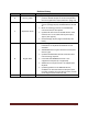
EMS D37 Female Connector Pin No. EMS D37 Connector Wire Color EMS Function EMS-D10 EMS-D100 MASTER POWER 1 RED SV-EMS-220 Function Sensor / Wiring Conversion To SV-EMS-220 VOLTMETER 1 (0-30 VOLTS DC) New capability; now used for monitoring voltage. In EMS-D10 and EMS-D100, this wire provided power input. In the FlightDEK-D180, power input was from the 25-pin EFIS connector, Pin 1. If connected to avionics power (EMS-D10, EMS-D100), OK for that connection to remain.
EMS D37 Female Connector Pin No. EMS D37 Connector Wire Color EMS Function SV-EMS-220 Function Sensor / Wiring Conversion To SV-EMS-220 If connected to Dynon P/N 100413-000 Carb Temp Sensor, remove the 1K resistor installed between this pin and Pin 18 (+5V Output). If connected to Dynon 100411000 Pressure Sensor for monitoring coolant, remove the 1K resistor installed between this pin and Pin 18 (+5V Output).
EMS D37 Female Connector Pin No. EMS D37 Connector Wire Color EMS Function SV-EMS-220 Function Sensor / Wiring Conversion To SV-EMS-220 9 BROWN/BLUE CONTACT 1 GENERAL PURPOSE INPUT 5 (TYPE A) No changes required. 10 BROWN/YELLOW CONTACT 2 GENERAL PURPOSE INPUT 6 (TYPE A) No changes required. 11 ORANGE SERIAL A TX GENERAL PURPOSE INPUT 7 (TYPE A) New capability – now a General Purpose input. Cut off the 9-pin connector to use this wire.
EMS D37 Female Connector Pin No. 19 20 21 EMS D37 Connector Wire Color WHITE/BLACK ORANGE/BROWN ORANGE/BLUE EMS Function SERIAL B RX FUEL LEVEL 1 / LEFT FUEL LEVEL 2 / RIGHT SV-EMS-220 Function Sensor / Wiring Conversion To SV-EMS-220 FUEL FLOW 2 New capability – now a second (differential) fuel flow sensor input. If connected, SkyView can display differential fuel flow. If connected to GPS or NAV input, reroute connection to SkyView display(s) serial port RX.
EMS D37 Female Connector Pin No. EMS D37 Connector Wire Color EMS Function SV-EMS-220 Function Sensor / Wiring Conversion To SV-EMS-220 If connected to Dynon P/N 100413-000 Carb Temp Sensor, remove the 1K resistor installed between this pin and Pin 18 (+5V Output). If connected to Dynon 100411000 Pressure Sensor for monitoring coolant, remove the 1K resistor installed between this pin and Pin 18 (+5V Output).
EMS D37 Female Connector Pin No. EMS D37 Connector Wire Color EMS Function SV-EMS-220 Function Sensor / Wiring Conversion To SV-EMS-220 New capability; can now accept voltage input similar to Pins 8, 22, and 31 (Enhanced General Purpose Inputs 4, 2, and 13 respectively). If connected to Dynon P/N 100413-000 Carb Temp Sensor, remove the 1K resistor installed between this pin and Pin 18 (+5V Output).
EMS D37 Female Connector Pin No. EMS D37 Connector Wire Color EMS Function SV-EMS-220 Function Sensor / Wiring Conversion To SV-EMS-220 26 GREEN/RED MANIFOLD PRESSURE MANIFOLD PRESSURE No changes required. (NO WIRE) GENERAL PURPOSE THERMOCOUPLE + (J OR K) GENERAL PURPOSE THERMOCOUPLE 1 + (J OR K) No changes required. 28 (NO WIRE) GENERAL PURPOSE THERMOCOUPLE - (J OR K) GENERAL PURPOSE THERMOCOUPLE 1 + (J OR K) No changes required.
EMS D37 Female Connector Pin No. 33 EMS D37 Connector Wire Color WHITE/BLUE 34 BLUE EMS Function RPM RIGHT EMS-D10 EMS-D120 DSAB B FlightDEK-D180 UNUSED 35 GREEN EMS-D10 EMS-D120 DSAB A FlightDEK-D180 UNUSED EMS-D10 EMS-D120 DSAB B 36 BLUE FlightDEK-D180 UNUSED EMS-D10 EMS-D120 DSAB A 37 GREEN FlightDEK-D180 UNUSED SV-EMS-220 Function STANDARD VOLTAGE RPM RIGHT Sensor / Wiring Conversion To SV-EMS-220 If connected to Rotax engine th (5 trigger coil), remove 30K resistor.
D10 and D100 Series Conversion To SkyView Guide – Rev D Page 28
Guidelines for Conversion of Dynon Avionics EMS CHT/EGT Harness to SkyView SV-EMS-220 CHT/EGT Harness The CHT/EGT 25-pin connector is “Plug and Play”. If the CHTs and EGTs were installed and working on the Dynon Avionics EMS and no changes are needed, there is no wiring conversion required to work with an SV-EMS-220. The CHT/EGT 25-pin female connector on the SV-EMS220 is electrically compatible with the CHT/EGT 25-pin female connector on a Dynon Avionics EMS.
EMS Sensor Type Conversion to SkyView Sensor Type Dynon EMS’ use numeric sensor types to specify what sensor is connected to a particular input. In SkyView SENSOR INPUT MAPPING, full names and often PNs are used.
EMS-D10 / EMS-D120 / FlightDEK-D180 Sensor Type Description in Manual SkyView Sensor Description SENSOR INPUT MAPPING Fuel Pressure Sensor – Type 1 Dynon P/N 100411-000 (Legacy 0-30 PSI carbureted) 0-30 PSI FLUID PRESSURE (100411-000) Fuel Pressure Sensor – Type 2 Dynon P/N 100411-001 (Legacy 0-80 PSI injected) 0-80 PSI FLUID PRESSURE (100411-001) Fuel Pressure Sensor – Type 3 GRT LPS-02 (remove the external pull-up resistor) This sensor is not supported in SkyView Fuel Pressure Sensor – Type 4 Stew
EMS-D10 / EMS-D120 / FlightDEK-D180 Sensor Type Description in Manual Oil Pressure – Type 1 Dynon P/N 100411-002 Rotax 912 pre-installed (prior to mid-2008) SkyView Sensor Description SENSOR INPUT MAPPING Check to see the type of sensor is actually installed on the engine: 0-150 PSI FLUID PRESSURE (100411-002) or ROTAX OIL PRESSURE (MECHANICAL) Oil Pressure – Type 2 GRT HPS-01 0-150 PSI FLUID PRESSURE (100411-002) Oil Pressure – Type 3 Jabiru pre-installed JABIRU OIL PRESSURE Oil Pressure – Type 4 Ro
EMS-D10 / EMS-D120 / FlightDEK-D180 Sensor Type Description in Manual SkyView Sensor Description SENSOR INPUT MAPPING Oil Temperature – Type 10 UMA 1B1 (1/8-27 NPT) UMA 1B3 (5/8-18 UNF) These sensors are not supported in SkyView Guidelines for Conversion of HS34 HSI Expansion ModuleD25 Male Connector to SV-HARNESS-D37 and SkyView SV-EMS-220 Main Sensor Harness As previously mentioned, the HS34 is not compatible with the SkyView system.
HS34 Male Connector Pin No. HS34 Male Connector Function Notes for conversion to SV-HARNESS-D37 and SV-EMS-220 Main Sensor Harness 6 GP OUTPUT 2 (not currently supported) Not used in SkyView system. Remove this wire.
HS34 Male Connector Pin No.
HS34 Male Connector Pin No.
HS34 Male Connector Pin No. 17 18 19 HS34 Male Connector Function Notes for conversion to SV-HARNESS-D37 and SV-EMS-220 Main Sensor Harness MASTER GROUND If this wire was used for connection to PC, no longer required; remove this wire.
HS34 Male Connector Pin No.
HS34 Male Connector Pin No. 25 HS34 Male Connector Function Notes for conversion to SV-HARNESS-D37 and SV-EMS-220 Main Sensor Harness VOICE AUDIO OUTPUT (8V peakpeak) If this wire was used for audio output, reroute this wire to SkyView display. Because HS34 Audio was mono, connect this wire to both SkyView Display PIN 13 – AUDIO OUTPUT LEFT and PIN 31 – AUDIO OUTPUT RIGHT If a 10K potentiometer was installed on this wire to adjust volume, remove it (SkyView has internal volume adjustment).
Guidelines for Conversion of HS34 HSI Expansion Module D25 Female Connector to SV-HARNESS-D37 and SkyView SV-EMS-220 Main Sensor Harness As previously mentioned, the HS34 is not compatible with a SkyView system. This chart explains the signals and wires that may be rerouted on the existing HS34 harness for conversion to a SkyView SV-ARINC-429 module. Dynon has never supplied a harness for HS34, so there are no standardized wire colors – you will have to match pin numbers with wire colors.
D25 Female Connector Pin No. HS34 Function SV-ARINC-429 Function Notes for conversion to SV-ARINC-429 12 ARINC 429 TX B ARINC TX B Reroute this wire to SV-ARINC-429 pin 12. Same signal as Pin 13 13 ARINC 429 TX B ARINC TX B Reroute this wire to SV-ARINC-429 pin. Same signal as Pin 12. 14 CDI + when Left Unused pin, not connected Not used in SkyView system. Remove this wire. 15 VOR + when From flag shown Unused pin, not connected Not used in SkyView system. Remove this wire.
Guidelines for Conversion of AP74 Dedicated Autopilot Interface Module to SV-HARNESS-D37 As previously mentioned, the AP74 is not used in the SkyView system. This chart explains the signals and wires (only the audio) that, if used, must be rerouted for conversion to a SkyView SV-HARNESS-D37. Dynon has never supplied a harness for AP74, so there are no standardized wire colors – you will have to match pin numbers with wire colors. AP74 Male Connector Pin No.
Guidelines for Conversion of Dynon Avionics Autopilot Servos The primary change for a servo converting to SkyView is that the servo’s White/Blue and White/Green wires (unused in Dynon Avionics EFIS systems) now need to be brought forward to connect to the SkyView Network along with the Blue and Green wires that previously connected to the EFIS and EMS DSAB network. Note: To connect to SkyView, Autopilot servos must have a (EFIS) firmware version installed of at least v5.2.
Guidelines for Conversion of Accessories The Dynon Heated AOA Pitot Probe Controller includes an output that is used to indicate failure of the heating system. Because of limited inputs on a Dynon Avionics EMS, this circuit was often wired to a separate indicator light. Because SkyView SV-EMS-220 has more available inputs, it is common to connect the “Heater Failure” output to the SV-EMS-220 which can then display the status of the “Heater Failure” (red, or green) on the SkyView EMS page.