Autopilot Servo Installation Guide CAPSTAN THIS PRODUCT IS NOT APPROVED FOR INSTALLATION IN TYPE CERTIFICATED AIRCRAFT DOCUMENT 101385-000, REVISION D January, 2013 Copyright © 2009-2012 by Dynon Avionics, Inc.
DYNON AVIONICS Contact Information Dynon Avionics, Inc. 19825 141st Place NE Woodinville, WA 98072 Phone: (425) 402-0433 - 8:00 AM – 5:00 PM (Pacific Time) Monday – Friday Dynon Technical Support available 7:00 AM–4:00 PM (Pacific Time) Monday – Friday Email: support@dynonavionics.com Fax: (425) 984-1751 Dynon Avionics offers online sales, extensive support, and frequently updated information on its products via its Internet sites: www.dynonavionics.com –Dynon Avionics primary web site; including: docs.
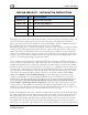
DYNON AVIONICS CAPSTAN SERVO KIT – INSTALLATION INSTRUCTIONS Dynon Part # QTY Part Description 100976-011 4 AN365-1032A Lock Nuts 100977-000 8 AN970-3 Large Washers 100981-003 4 AN3H-6A Bolts - 3/4" 101056-000 4 Cable Clamps 101113-000 1 Bridle Cable Assembly The capstan servo accessory kit includes the hardware necessary to attach one autopilot servo to one axis of the aircraft controls.
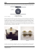
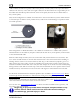
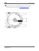
DYNON AVIONICS in the center groove. Set the cable swage into the hole in the pulley and pass the other end of the bridle cable under the opposite flange. Feed both cable ends around the pulley and underneath the next set of cable guard flanges following the grooves. With the cable properly fed into the pulley, install the servo in the mount. Rotate the capstan until the installed swage sits on the opposite side of the pulley from where the bridle cable exits the servo (see figure 1).
DYNON AVIONICS cable would be attached to separate cables in the primary control system; ie the "up" and "down" cables for the elevator, or the "left" and "right" cables for the aileronNote: the swaged index pin on the bridle cable should be positioned in the center of the pulley between the two bridle cables as they exit the pulley.
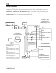
DYNON AVIONICS Wiring Overview The following diagram provides an overview of the autopilot-specific wiring installation. For the complete set of wiring and configuration instructions, please see the latest Installation Guide for your Dynon EFIS product. For a SkyView system please reference the Autopilot Servo Installation, Configuration, and Calibration chapter of your SkyView System Installation guide.
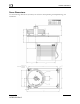
DYNON AVIONICS Servo Dimensions Use the following dimensions (in inches) for reference when planning and implementing your installation.
DYNON AVIONICS The autopilot safety shear screw should NEVER be removed or adjusted during this operation. If the shear screw has broken and needs replacement, there is specific documentation available for this purpose at http://docs.dynonavionics.com.