©2005 Dynojet Research, Inc. All Rights Reserved. Analog Module Installation and User Guide This manual is copyrighted by Dynojet Research, Inc., hereafter referred to as Dynojet, and all rights are reserved. This manual, as well as the software described in it, is furnished under license and may only be used or copied in accordance with the terms of such license. This manual is furnished for informational use only, is subject to change without notice, and should not be construed as a commitment by Dynojet.
TABLE OF CONTENTS Chapter 1 Analog Module Installation Introduction . . . . . . . . . . . . . . . . . . . . . . . . . . . . . . . . . . . . . . . . . . . . . . . . . . 1-2 Conventions Used In This Manual . . . . . . . . . . . . . . . . . . . . . . . . . . . . . . . 1-2 Technical Support . . . . . . . . . . . . . . . . . . . . . . . . . . . . . . . . . . . . . . . . . . . 1-2 Parts List . . . . . . . . . . . . . . . . . . . . . . . . . . . . . . . . . . . . . . . . . . . . . . . . . .
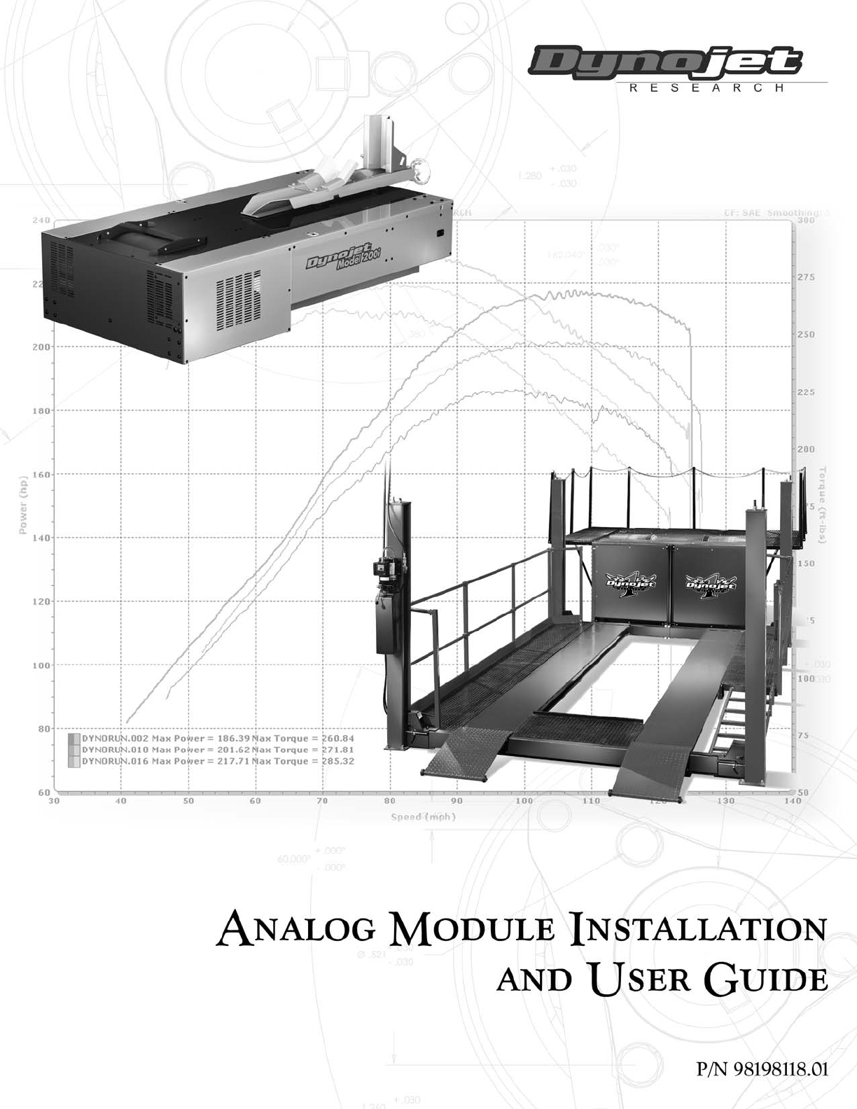
CHAPTER 1 ANALOG MODULE INSTALLATION This document provides instructions for installing and using the Analog Module with WinPEP 7. To ensure safety and accuracy in the procedures, perform the procedures as they are described. This chapter will walk you through installing the Analog Module, routing the Analog Module cable assembly, and connecting the sensor cables. Chapter two will walk you through configuring your Analog Module and viewing the data.
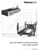
CHAPTER 1 Introduction INTRODUCTION ................................... The Analog Module, when added to Dynojet's market leading inertia dynamometer, results in a complete vehicle performance test. The Analog Module is capable of measuring any 0-5 volt signal on a vehicle and comes with an unterminated cable to allow you to hook up your own sensors. Additional sensors and cables are available from Dynojet.
ANALOG MODULE INSTALLATION Analog Module Installation ANALOG MODULE INSTALLATION ................................... This section describes how to access the dyno electronics, install the Analog Module, route the Analog Module cable assembly, and connect the sensor cables. CONNECTING AND DISCONNECTING POWER TO THE DYNO Always disconnect the power before beginning any installation procedures. Refer to your dyno installation manual for more information on disconnecting the power to your specific dyno.
CHAPTER 1 Analog Module Installation 4 5 Add the Analog Module to the top of the dyno electronics. Refer to “Installing the Analog Module” on page 1-5. Leave the dyno electronics enclosure out. You will need to route any sensor cables to the Analog Module as they are installed.
ANALOG MODULE INSTALLATION Analog Module Installation INSTALLING THE ANALOG MODULE 1 2 3 Verify the main dyno power is disconnected. Turn off the main power switch on the CPU Module and unplug the power cord. Remove the dust cover from the existing top module. dust cover power cord input power switch Figure 1-3: Remove Dust Cover 4 5 6 7 Loosen the top right screw on the back of the existing top module. Plug the Analog Module into the existing top module.
CHAPTER 1 Analog Module Installation ROUTING THE ANALOG MODULE CABLE ASSEMBLY 1 2 Route the Analog Module cable assembly through the cable clamp on the back of the dyno electronics enclosure. 1a Loosen the two screws and lift the clamp up to slide the analog cable through. 1b Secure the clamp with the two screws. Attach the connector on the Analog Module cable assembly to the front of the Analog Module.
ANALOG MODULE INSTALLATION Analog Module Installation CONNECTING THE SENSOR CABLES 1 2 Attach the sensor cable(s) to the Analog Module cable assembly. The two types of sensor cables are described below and shown in Figure 1-6. • An unterminated sensor cable, included with your Analog Module, is designed to connect directly to or “tap into” the vehicle’s existing sensors.
CHAPTER 2 ANALOG CHANNEL CONFIGURATION AND VIEWING DATA This chapter provides instructions for configuring the Analog Module and viewing the data with WinPEP 7. To ensure safety and accuracy in the procedures, perform the procedures as they are described.
CHAPTER 2 Analog Channel Configuration ANALOG CHANNEL CONFIGURATION ................................... You can configure up to four different analog channels. Use the following instructions to configure the analog channel(s). CONFIGURING THE ANALOG CHANNEL(S) 1 2 Verify you are in the MakeRun screen. Verify you are connected to the dyno electronics. Note: You must be connected to the dyno electronics and the Analog Module must be installed for the analog channels to be available.
ANALOG CHANNEL CONFIGURATION AND VIEWING DATA Analog Channel Configuration 7 8 Choose a sensor from the drop down list. Click OK. sensor drop down list Figure 2-2: Analog Sensor Helper Window—Choose a Sensor 9 Enter the analog channel name in the Display Name field. 10 Click OK to enter these changes or click Cancel to abort the changes and return to the MakeRun screen.
CHAPTER 2 Analog Channel Configuration CUSTOMIZING SENSOR TABLES Some sensors may require additional rows. You may customize your sensor table by adding or removing rows. 1 2 Right click on the table. Choose Add Row or Remove Row to customize your table.
ANALOG CHANNEL CONFIGURATION AND VIEWING DATA Analog Channel Configuration SAVING AND LOADING SENSOR TABLES Commonly used sensor tables may be saved to a file allowing you to load and use them later. 1 2 3 4 Click Save Sensor Table to save the sensor table to a file. Choose a location and click Save. Click Load Sensor Table to load a saved sensor table. Click OK to load the sensor table or click Cancel to abort the changes and return to the MakeRun screen.
CHAPTER 2 Analog Channel Configuration EDITING A GAUGE You will need to either create a new gauge or edit an existing gauge to represent your analog channel. For this example, we will edit an existing gauge. For more detailed information on creating a gauge, refer to the WinPEP 7 manual. 1 2 3 4 5 Verify you are in Advanced Mode. To change the user level click Tools Environment Options and click on the General tab. If you are not already there, go to the MakeRun screen. Click the Make Run button .
ANALOG CHANNEL CONFIGURATION AND VIEWING DATA Viewing Data VIEWING DATA ................................... Once the analog channel is configured, the information will automatically be recorded when you make a run. 1 2 Make your dyno run. Refer to the dyno installation and WinPEP 7 manuals for more detailed information on making a run. By default, a graph of your run will appear. In order to view the analog channel data recorded, you will need to configure your graph to show the analog channel.