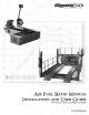
©2000-2004 Dynojet Research, Inc. All Rights Reserved. Air Fuel Ratio Module Installation and User Guide. This manual is copyrighted by Dynojet Research, Inc., hereafter referred to as Dynojet, and all rights are reserved. This manual, as well as the software described in it, is furnished under license and may only be used or copied in accordance with the terms of such license.
TABLE OF CONTENTS Chapter 1 Air Fuel Ratio Module Installation Introduction . . . . . . . . . . . . . . . . . . . . . . . . . . . . . . . . . . . . . . . . . . . . . . . . . . 1-2 Warnings . . . . . . . . . . . . . . . . . . . . . . . . . . . . . . . . . . . . . . . . . . . . . . . . . . 1-2 Conventions Used In This Manual . . . . . . . . . . . . . . . . . . . . . . . . . . . . . . . 1-3 Technical Support . . . . . . . . . . . . . . . . . . . . . . . . . . . . . . . . . . . . . . . . . . .
CHAPTER 1 AIR FUEL RATIO MODULE INSTALLATION This document provides instructions for installing and using the Air Fuel Ratio Module and version three of the Air Pump Assembly with WinPEP 7. Appendix A includes instructions for using the Air Fuel Ratio Module with WinPEP 6. To ensure safety and accuracy in the procedures, perform the procedures as they are described.
CHAPTER 1 Introduction INTRODUCTION ................................... The Air Fuel Ratio Module is designed to accurately sample air fuel ratios from engines burning petroleum based fuels. Be sure to read and follow all warnings found throughout this manual. Note: The Air Pump Assembly has a one year warranty. WARNINGS The sensor and the copper sample tube are hot. Before touching the sensor or the sample tube, make sure it has cooled.
AIR FUEL RATIO MODULE INSTALLATION Introduction CONVENTIONS USED IN THIS MANUAL The conventions used in this manual are designed to protect both the user and the equipment. Example of Convention Description The Caution icon indicates a potential hazard to the dynamometer equipment. Follow all procedures exactly as they are described and use care when performing all procedures. The Warning icon indicates potential harm to the person performing a procedure and/or the dynamometer equipment.
CHAPTER 1 Installation INSTALLATION ................................... This section describes installation procedures for the Air Fuel Ratio Module. PARTS LIST The following table lists all of the parts included in the Air Fuel Ratio Module Installation kit. Check your kit against the parts listed to make sure you have received all of the parts. If any part is missing, contact Dynojet Technical Support.
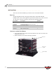
AIR FUEL RATIO MODULE INSTALLATION Installation 3 4 5 Loosen the top right screw on the back of the existing top module. Plug the Air Fuel Module into the existing top module. Place the dust cover, removed in step 2, on the Air Fuel Module. Secure the grounding strap on the back of the Air Fuel Module to the existing top module. grounding strap Figure 1-2: Secure Grounding Strap 6 7 8 Secure the Air Fuel Module to the stack with the plastic tie straps (one on each side).
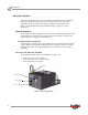
CHAPTER 1 Air Pump Assembly AIR PUMP ASSEMBLY ................................... This section describes how to set up the Air Pump Assembly. Dynojet recommends running the pump between dyno runs to help reduce the chance of moisture contamination on the sensor. Always keep the pump in the upright position. Refer to “Air Pump Maintenance and Troubleshooting” on page 2-7 for more information.
CHAPTER 2 USING THE AIR FUEL RATIO MODULE This chapter will walk you through the set up procedures, sampling and viewing air fuel ratios, and how to maintain and troubleshoot your air pump. To ensure safety and accuracy in the procedures, perform the procedures as they are described.
CHAPTER 2 Module and Pump Set Up MODULE AND PUMP SET UP ................................... This section describes the set up procedures for the Air Fuel Ratio Module and Air Pump Assembly. 1 2 Run the vehicle and allow the vehicle to warm up. Excess condensed water is produced during warm up which can damage the Air Pump Assembly. Allowing the vehicle to warm up removes this excess water. Place the copper sample tube in the exhaust pipe of the test vehicle.
USING THE AIR FUEL RATIO MODULE Sample and View Air Fuel Ratios SAMPLE AND VIEW AIR FUEL RATIOS ................................... This section describes the procedures to sample and view air fuel ratios using WinPEP 7. If you are using WinPEP 6, refer to Appendix A. Note: Allow the sensor to preheat before making a run. An orange LED light on the Air Fuel Ratio Module will light up continuously when the sensor is ready to make a run. SAMPLING AIR FUEL RATIOS 1 2 3 Verify you are in the MakeRun screen.
CHAPTER 2 Sample and View Air Fuel Ratios 4 5 Verify the Air Pump Assembly is on. Press the green sample button on the pendent to begin recording data. Note: For more information on how to make a run, refer to the WinPEP 7 User Guide (on your WinPEP CD or at www.dynojet.com/manuals.shtml) or the WinPEP 7 Online Help. 6 Press the sample button a second time to stop sampling.
USING THE AIR FUEL RATIO MODULE Sample and View Air Fuel Ratios VIEWING AND GRAPHING AIR/FUEL RUNS For more information about graph functions and displays, refer to the WinPEP 7 User Guide (on your WinPEP CD or at www.dynojet.com/manuals.shtml) or the WinPEP 7 Online Help. 1 2 3 Verify you are in the Graph screen. Select File !Open. Browse the directory and select a run file. You may also select multiple run files. A preview of the graph will appear.
CHAPTER 2 Sample and View Air Fuel Ratios The run information is displayed in the ListView along with a graph of the run. 5 Click on the axis channel label and choose Air/Fuel from the list. Note: Available channels may differ depending on your dyno model and configuration. The graph will now display the run with air/fuel readings.
USING THE AIR FUEL RATIO MODULE Air Pump Maintenance and Troubleshooting AIR PUMP MAINTENANCE AND TROUBLESHOOTING ................................... This section contains sensor information and describes the procedures for maintaining and troubleshooting the Air Pump Assembly. Note: Make sure you are aware of the following items: • The Air Pump Assembly has a one year warranty. • Keep the air pump upright. Tipping the pump may result in damage to the sensor.
CHAPTER 2 Air Pump Maintenance and Troubleshooting IF WATER IS COLLECTING IN THE FILTER BOWL Do not allow the filter bowl to fill with water during operation. Use the following instructions to troubleshoot excess water in the filter bowl. 1 2 3 Unscrew the filter bowl from the filter housing and verify there is no blockage in the filter bowl. Verify the fitting at the bottom of the bowl is not clogged. Clean if necessary. Turn the pump on and check for air flow through the small hose.
USING THE AIR FUEL RATIO MODULE Air Pump Maintenance and Troubleshooting 5 6 7 8 9 10 11 12 13 Remove the small hose from the fitting on the pump head. Turn the pump on and check for air flow into the pump head. If there is no air flow at the pump head, refer to “Pump Head Maintenance” on page 2-12. If there is air flow, continue with the next step. Turn the pump off and disconnect the power cable from the pump assembly.
CHAPTER 2 Air Pump Maintenance and Troubleshooting CLEANING THE FILTER ASSEMBLY The air pump filter should be cleaned daily or more often depending on usage. The filter should be cleaned more often when the Air Fuel Ratio Module is used with twostroke engines, new silencers, or any other condition that introduces solids into the exhaust flow. Running the pump with the filter clogged, hose kinked, or filter removed will damage the pump and void the warranty.
USING THE AIR FUEL RATIO MODULE Air Pump Maintenance and Troubleshooting FILTER ASSEMBLY REPLACEMENT PARTS Refer to the table below and Figure 2-11 when ordering replacement parts.
CHAPTER 2 Air Pump Maintenance and Troubleshooting PUMP HEAD MAINTENANCE To ensure accurate readings, pump head maintenance should be performed every six months, or sooner, depending on usage. One pump head maintenance kit (P/N 79190003) has been included with your pump purchase. Disregard the foam insert included in the kit. The pump has two pump heads. Use the following instructions to clean and maintain each pump head. Note: Dynojet recommends cleaning one pump head at a time. 1 2 Remove the sensor.
USING THE AIR FUEL RATIO MODULE Air Pump Maintenance and Troubleshooting 4 5 Note the orientation of the pump heads using the stickers or the letters on the top of the head as a marker. The inlet side of each head is labeled B while the outlet side is labeled A Note: The pump head must be re-installed correctly or the pump will not function properly. Using a T-20 Torx driver, remove the four screws securing the pump head and remove the head. Note: Do not remove the pump from the housing.
CHAPTER 2 Air Pump Maintenance and Troubleshooting 6 Mark the orientation of the valve plate with the pump head before removing the valve plate. You may also use the letters on the top of the pump head to ensure correct orientation. 7 Note: The valve plate must be re-installed correctly or the pump will not function properly. Remove the four No. 2 phillips head screws securing the valve plate and remove the plate.
USING THE AIR FUEL RATIO MODULE Air Pump Maintenance and Troubleshooting 8 Mark the orientation of each reed valve with the valve plate. Note: The reed valve must be re-installed correctly or the pump will not function properly. Note: Dynojet recommends you remove and clean one reed valve at a time. 9 Using a flat-head screwdriver, remove the screw securing the reed valve. Remove the washer and valve. 10 Carefully clean the area where the reed valve seats. 11 Carefully clean the reed valve.
CHAPTER 2 Air Pump Maintenance and Troubleshooting 15 Check the condition of the diaphragm. If the diaphragm is cracked or deteriorated, replace the diaphragm. 15a Remove the four No. 2 phillips head screws securing the mounting plate and remove the plate. 15b Inspect the diaphragm and replace if necessary. 15c Secure the mounting plate with the screws you removed earlier. Note: Be sure the screws securing the mounting plate are the smaller of the flathead screws.
USING THE AIR FUEL RATIO MODULE Air Pump Maintenance and Troubleshooting REPLACING THE FUSE The air pump has a 3 amp 250 volt 5mm fuse located in a drawer just above the power cord plug in. The fuse drawer contains the fuse and a spare fuse. Once you use the spare fuse, remember to replace it with a new one. 1 2 Disconnect the power cable from the Air Pump Assembly. The fuse drawer will not come out until the power cable is removed.
CHAPTER 2 Air Pump Maintenance and Troubleshooting EMPTYING THE EXHAUST COLLECTION BOTTLES Remember to remove and empty the exhaust collection bottles located at the back of the Air Pump Assembly regularly.
APPENDIX A AIR FUEL RATIOS WITH WINPEP 6 This appendix provides instructions for using the Air Fuel Ratio Module with WinPEP 6. To ensure safety and accuracy in the procedures, perform the procedures as they are described.
APPENDIXA Sample and View Air Fuel Ratios Using WinPEP 6 SAMPLE AND VIEW AIR FUEL RATIOS USING WINPEP 6 ................................... This section describes the procedures to sample and view air fuel ratios using WinPEP 6. For more information on making and graphing a run, refer to your dynamometer user guide located on your WinPEP CD or at www.dynojet.com/manuals.shtml. Note: Allow the sensor to preheat before making a run.
AIR FUEL RATIOS WITH WINPEP 6 Sample and View Air Fuel Ratios Using WinPEP 6 4 Click MakeRun. The following speedometer and tachometer window appears. This window has an air fuel ratio meter with a multi-colored meter and numerical value display. A numerical air fuel ratio number higher than zero, or an orange light on the Air Fuel Ratio Module, indicates that the sensor is ready for sampling.
APPENDIXA Sample and View Air Fuel Ratios Using WinPEP 6 UTILIZING DYNOTRAC The following speedometer and tachometer window appears while utilizing DynoTrac software for the Proportional Air Control or the Eddy Current Brake system. This window has an air fuel ratio meter with a multi-colored meter and numerical value display. Note: Run data will not be recorded in this configuration.
AIR FUEL RATIOS WITH WINPEP 6 Sample and View Air Fuel Ratios Using WinPEP 6 VIEWING AND GRAPHING AIR/FUEL RUNS Select the runs you wish to view on the graph. Refer your dynamometer user guide for more information on viewing graphs. 1 2 3 4 Verify you are in the Graph screen. Select and open the run file you wish to view. Right click on the graph and select Graph Options. Click Axis Selection. Note: You may want to deselect the Force Scaling option when looking at air fuel ratios.
APPENDIXA Sample and View Air Fuel Ratios Using WinPEP 6 6 Select an option from the list to graph on the right Y axis. Air/Fuel was selected in this example. Figure A-6: Graph Options Window—Right Y Axis 7 Select an option from the list to graph on the X axis. Engine RPM was selected in this example.
AIR FUEL RATIOS WITH WINPEP 6 Sample and View Air Fuel Ratios Using WinPEP 6 8 Select the gear ratio by clicking the right mouse button. Note: This menu will only appear if you choose Engine RPM in step 7. Figure A-8: Graph Options Window—Gear Ratio The main graph containing the run and options you selected is now displayed.