
Installation Guide Owner's manual

In Ground Model 200iP/250iP Motorcycle Dynamometer Installation Guide
CHAPTER 2
Routing Cables
2-40
ROUTING THE PICKUP CARD AND DYNO ELECTRONICS CABLES
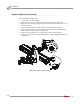
1 Route the pickup card cable (P/N 66953002) from the CPI through the designated
pit conduit and over to the pickup card. Attach the cable to the pickup card.
Note: Be sure to keep the power and communications cables in different pit
conduits.
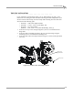
2 Route the 25-pin cable (P/N 42924251) from the dyno electronics input/output
module to the Breakout board. Refer to Figure 2-37 for Breakout board location.
Refer to “Dyno Electronics” on page 1-10 for the 25-pin cable location.
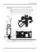
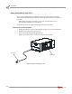
3 Route the 9-pin serial cable (P/N 42967090) from the dyno electronics CPU
Module to your computer. Refer to “Dyno Electronics” on page 1-10 for the
9-pin serial cable location.
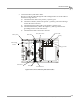
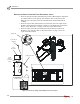
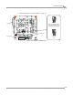
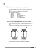
Figure 2-35: Route the Pickup Card and Dyno Electronics Cables
PD170
pickup card
dyno
electronics
CPI
25-pin cable to
breakout board
9-pin cable to
computer
pickup card cable
25-pin
cable to
breakout
board