
Installation Guide Owner's manual

In Ground Model 200iP/250iP Motorcycle Dynamometer Installation Guide
CHAPTER 1
Dynamometer Specifications and Requirements
1-8
COMPRESSED AIR REQUIREMENTS
The following requirements are needed when the optional air brake is included.
• regulator set to 65 psi max (450 kilopascal)
•air dryer
• shut off valve
• gauge on the regulator
• 1/4-inch NPT pipe thread connector (to attach air to the dyno)
COMPUTER SPECIFICATIONS
You will need to provide a computer system to run the WinPEP software. WinPEP 7
includes complete documentation in online Help. From the WinPEP 7 menu bar,
choose Help
WinPEP 7 Help or visit www.winpep.com (accessible with a valid user
name and password). Refer to the section on Computer Specifications in the WinPEP
documentation, P/N 98118103, for the specific computer system requirements.
DRILL AND DRILL BIT REQUIREMENTS
You will need to provide a drill and drill bit capable of drilling holes in concrete. Refer
to Appendix A for more information on installing Red Head Anchors.
• drill bit size: 1/2-inch
• minimum hole depth: 1 5/8-inch (41.2 mm)
ELECTRICAL REQUIREMENTS
The Model 200iP/250iP dynamometers require a 240V - 30a single-phase electrical
circuit for reliable and precise operation. No other loads should be plugged into these
circuits and these circuits should be independent of the lighting in the dyno room.
Before you plug in your dyno, you or your electrician must refer to Appendix B for
detailed information.
ENVIRONMENTAL REQUIREMENTS
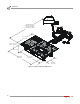
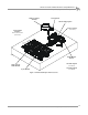
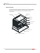
FORKLIFT REQUIREMENTS
You will need to provide equipment capable of lifting a minimum of 1,043 kg.
(2300 lb.) to lift the dyno off the crate and into position in your dyno room. You will
also need a pair of straps capable of supporting 1,043 kg. (2300 lb.) to attach to the
dyno. Dynojet recommends using single loop style straps.
description specifications
Tempe r a t ure
operating min./max 10°C/50°C (50°F/122°F)
storage min./max 0°C/60°C (32°F/140°F)
Humidity 0 to 95% non condensing