
Upgrade (S/N 202xxxx) Owner's manual

10
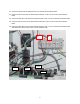
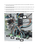
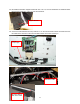
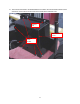
27. Connect the brown wire from the top left connection of the lower 15A circuit breaker to Tab 8 on the
Control Panel Interface board.
28. Connect the blue wire from the bottom left connection of the lower 15A circuit breaker to Tab 7 on the
Control Panel Interface board.
29. Connect the brown wire from the top left connection of the upper 15A circuit breaker to Tab 6 on the
Control Panel Interface board.
30. Connect the blue wire from the lower left connection of the upper 15A circuit breaker to Tab 5 on the
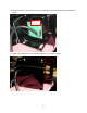
Control Panel Interface board. Cable tie as shown. Cut the cable ties flush.
Tab 5
Tab 6
Tab 7
Tab 8
Upper
15A
Breaker