©2004 Dynojet Research, Inc. All Rights Reserved. Control Panel Interface Upgrade Installation Guide For Model 200i and 250i Motorcycle Dynamometers Serial Number 202xxxx. This manual is copyrighted by Dynojet Research, Inc., hereafter referred to as Dynojet, and all rights are reserved. This manual is furnished under license and may only be used or copied in accordance with the terms of such license.
April 12, 2004 Control Panel Interface upgrade for 200i/250i Dynos Serial Number 202xxxx These instructions are intended for use with installing the Control Panel Interface upgrade into Dynojet Research model 200i and 250i dynos with a serial number prefix of 202. Before proceeding, check the serial number on the dyno front left corner to verify it is in this range. The Dynojet part number for this upgrade is P/N 78121003.
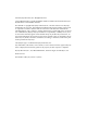
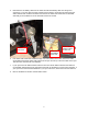
2. Once the covers are off, inspect your dyno to verify that the starter brace is installed. If your dyno does not have a starter brace, contact Dynojet. The starter brace can be ordered under the P/N 21721200 Starter Brace, M/C3. The starter brace supports the back of the starter and provides a good ground connection. Starter Brace 3. If a battery is installed, disconnect the negative terminal of the battery first then remove the positive terminal. If any battery charger has been installed, remove it.
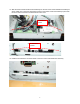
. Disconnect the red battery cable from the starter and the black battery cable from the ground connection. If your dyno does not have a starter brace as shown, contact Dynojet. Disconnect the starter solenoid wire. All wires should be removed from the starter. Disconnect the red and black wires that go into the black box on the back wall of the drum module. Remove these wires Disconnect Yellow/Black twisted wire Remove Red and Black wires at other end 6.
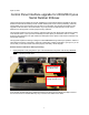
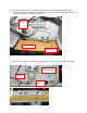
9. Disconnect the white 4 pin connector from the DIN barrier strip rail on the back side of the Power Distribution assembly to the lower fuse panel assembly. Disconnect the Air Pump power connector on the front side of the Power Distribution assembly. DIN barrier strip Fuse sub panel Disconnect this connector 10. Remove the two screws that hold the fuse sub panel in place then remove the panel and set aside.
11. Disconnect the blue and brown wires that connect from the DIN barrier strip on the back of the Power Distribution assembly from the 15A fan breakers. Pull only on the quick lug connectors on the back of the breakers and take care to not pull on the wires. Do not disturb any other connections.
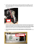
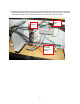
12. Remove the power supply bracket by cutting the cable ties and removing the two 8-32 screws from the front side of the Power Distribution assembly and save for later use. Power Supply Bracket 13. Install the new power supply bracket, which has the power supply installed, with the two 8-32 screws from the front side of the Power Distribution assembly.
14. Slide the Control Panel Interface board assembly into the rear of the Power Distribution assembly as shown. Make sure to have the sheetmetal centered in the guides. Fasten the assembly in place with two 8-32 x 3/8-inch screws in the back and two in the front. 8-32x3/8-inch screws 8-32x3/8-inch screws 15. Install the P/N 97422010 connector sticker to the front of the Power Distribution assembly.
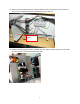
16. Route the fan breaker and Control Panel Interface wires. You will need the wiring harness kit P/N 76910601. 17. Connect the 5.5-inch blue wire labeled H to the lower left lug of the 15A circuit breaker. 18. Connect the 8-inch blue wire labeled I to the lower left lug of the upper 15A circuit breaker. 19. Connect the 6-inch brown wire labeled J to the top left lug of the bottom 15A circuit breaker. 20. Connect the 9-inch brown wire labeled K to the top left lug of the upper 15A circuit breaker.
22. Connect the wires from the DIN power rail to the Control Panel Interface board. 23. Connect the brown wire from the bottom DIN terminal #1 to Tab 4 on the Control Panel Interface board. 24. Connect the blue wire from the bottom DIN terminal #4 to Tab 3 on the Control Panel Interface board. 25. Connect the brown wire from the bottom DIN terminal #2 to Tab 2 on the Control Panel Interface board. 26. Connect the blue wire from the bottom DIN terminal #5 to Tab 1 on the Control Panel Interface board.
27. Connect the brown wire from the top left connection of the lower 15A circuit breaker to Tab 8 on the Control Panel Interface board. 28. Connect the blue wire from the bottom left connection of the lower 15A circuit breaker to Tab 7 on the Control Panel Interface board. 29. Connect the brown wire from the top left connection of the upper 15A circuit breaker to Tab 6 on the Control Panel Interface board. 30.
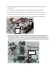
31. Route the wiring to the optional Wheel Clamp and Power Carriage through the dyno. You may find it easier to slide the Stack Box out of the side of the dyno and remove its support bracket for routing these cables. Even if you have not purchased these optional accessories it is better to install the cables now for an easy upgrade in the future. Remove bracket 32. Remove the front cable access plate.
33. Route the P/N 76950308 Pod to Carriage cable from P8 on the Control Panel Interface board to the front cable hole on the dyno. The cable passes under the center partition in the carriage module and in front of the vertical angle. Make sure that the cable strain relief end with the conduit nut is at the end of the cable that will connect to the carriage. The strain relief for both the Power Carriage and the Wheel Clamp must end up outside of the dyno. Strain relief 34.
35. Re-install the Stack Box support bracket with four ¼-20 x ½ -inch hex head bolts. Re-install the Stack Box and secure with four ¼-20 x ½ -inch hex head bolts. Support Bracket 36. Connect the P/N 76950403 Air Pump cable to P11 on the Control Panel Interface front side and route the cable out the rear hole on the Control Panel Interface to the back of the dyno.
37. If you have an air brake, install P/N 76950110 cable into P7 in the Control Panel Interface board and run the short cable to the Breakout board as shown and connect. Cable tie as shown and route the other end to the air brake solenoid. Strip back the wires to the brake air solenoid and crimp into the barrel connections on the P/N 76950110 Air Brake cable. If you do not have an air brake, then skip installing this cable.
38. Route the wire harness to the Control Panel assembly. Depending on the location of the monitor upright, the wire harness can be routed to either side of the dyno. The P/N 76951501 cable plugs in the Control Panel Interface board P4. This cable should be cable tied to the Power Distribution assembly to make sure the cable does not pull on the board. Cable tie here P4 39. If you do not have a monitor tray and stand it will be necessary to purchase one from Dynojet to mount the Control Panel assembly.
40. Early production Monitor Arms, uprights, and the monitor tray may not have the tapped holes for routing the Control Panel cables and mounting the Control Panel. If your monitor stand arms do not have these holes, it will be necessary for you to drill and tap the holes in the monitor upright and the arms to allow for attaching the Control Panel cable bundle. The cable bundle needs to be arranged across the monitor arms to allow for easy movement of the monitor stand without pulling on the cables.
41. The Control Panel needs to be disassembled so the cable to the Control Panel Interface can be connected. Remove the screw and nuts shown and lift off the back/side cover.
42. Connect the Control Panel cable to the Control Panel Button board. Cable tie the incoming cable as shown. Cable tie here 43. Replace the Control Panel cover with the hardware that you removed before.
44. Mount the Control Panel to the side of the monitor tray. The cable lengths are set to allow installing the Control Panel on either side of the monitor tray for easy access. Route the cable bundle along the arms with service loops to allow movement. Make sure that during normal arm movement the cable does not get pinched.
45. The battery cables and starter cables need to be connected next. The 4 pin connector plugs into the back side of the Control Panel Interface board near the middle of the board to P2. The cable routes out of the back of the Power Distribution assembly as shown. P2 Route here and cable tie Battery to Control Panel Interface cable 46. Install the starter support bracket, if necessary, and connect the other end of the battery cables to the starter as shown.
47. Route the cables to the cable support bracket as shown. Cable tie as shown. Make sure that all of the cables clear any moving components. Only connect the positive terminal on the battery at this time. If this is the first time you have installed a battery in this dyno refer to the dyno install guide for instructions on installing the battery hold down bracket.
48. If you purchased either the Wheel Clamp or the Motorized Carriage, position the Motorized Carriage motor and/or the Wheel Clamp close to the dyno and plug in their motor cables for testing.
49. If you have an air brake and your dyno room is equipped with a safety switch on the door, it is necessary to connect the safety switch to the Control Panel Interface board interlock input to apply the air brake whenever the dyno room door is open. Connect the wires feeding the switch contacts to Interlock 1-A and Interlock 6-B connection points on the Control Panel Interface board. The board is shipped with a jumper wire in this location.
51. Turn on the main breaker on side of the dyno by moving it to the up position. Make sure the E-Stop button on the Control Panel is in the out position. Twist if necessary to take it out of E-Stop. Turn on the switch on the front of the Stack box. 52. If you have the optional High Speed Blowers, verify they are plugged in to the sides of the dyno then press the fan control buttons on the Control Panel and verify that the fans turn on and off. Press once to turn on and once to turn off. 53.
54. If you purchased the optional Wheel Clamp then press the left hand clamp button and verify that the Wheel Clamp closes. Release the button. Press the right hand clamp button first then press the left hand clamp button and hold both buttons to open the clamp. Refer to the user’s manual for more details of the operation. 55. If you purchased the optional Motorized Carriage then press the carriage forward and back buttons and verify carriage movement.
57. Install the door stop chain with the two 8-32 nuts. 58. Put the carriage module cover back on. Put the drum and retarder module covers back on. Install the carriage. 59. Plug the dyno power cable in and turn on the main breaker on the power distribution assembly. Turn on the power switch on the front of the stack box. Start up the WinPEP software and verify that the program still communicates to the dyno hardware. 60. Press the starter switch and hold to verify starter operation.