©2007 Dynojet Research, Inc. All Rights Reserved. Eddy Current Brake Driveline Upgrade Installation Guide for Model 250 Motorcycle Dynamometers This manual is copyrighted by Dynojet Research, Inc., hereafter referred to as Dynojet, and all rights are reserved. This manual, and the software described in it, is furnished under license and may only be used or copied in accordance with the terms of such license.
TABLE OF CONTENTS Driveline Upgrade Installation Introduction . . . . . . . . . . . . . . . . . . . . . . . . . . . . . . . . . . . . . . . . . . . . . . . . . . . 2 Conventions Used In This Manual . . . . . . . . . . . . . . . . . . . . . . . . . . . . . . . . 2 Technical Support . . . . . . . . . . . . . . . . . . . . . . . . . . . . . . . . . . . . . . . . . . . . 2 Remove the Existing Connecting Arms and Couplers . . . . . . . . . . . . . . . . . 3 Removing the Hood . . . . . . . . . . . . . . . . . . .
DRIVELINE UPGRADE INSTALLATION This document provides instructions for removing the existing coupler and mounting arms and upgrading to the new driveline and brace assemblies. To ensure safety and accuracy in the procedures, perform the procedures as they are described.
DRIVELINE UPGRADE INSTALLATION Introduction INTRODUCTION ................................... Before upgrading the driveline assembly, please take a moment to read this guide for installation instructions and other important information. CONVENTIONS USED IN THIS MANUAL The conventions used in this manual are designed to protect both the user and the equipment. example of convention description The Warning icon indicates potential harm to the person performing a procedure and/or the dynamometer equipment.
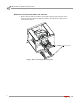
DRIVELINE UPGRADE INSTALLATION Remove the Existing Connecting Arms and Couplers REMOVE THE EXISTING CONNECTING ARMS AND COUPLERS ................................... This section will walk you through removing the eddy current brake from the dyno and removing the existing connecting arms and couplers. You will need to provide equipment capable of moving the eddy current brake. REMOVING THE HOOD 1 2 Remove the four bolts securing the eddy current brake cover and set aside.
DRIVELINE UPGRADE INSTALLATION Remove the Existing Connecting Arms and Couplers 3 Remove the four bolts securing the hood to the dyno and set aside. Prop up the hood. 4 5 If present, disconnect the wires to the key switch. Remove the hood from the dyno and set aside.
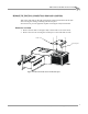
DRIVELINE UPGRADE INSTALLATION Remove the Existing Connecting Arms and Couplers REMOVING THE EDDY CURRENT BRAKE 1 2 Remove the three 3/8-inch bolts from the coupler. Loosen the set screws securing the coupler. set screws bolts Figure 3: Loosen the Couplers 3 4 Remove the four bolts and washers securing the connecting arms to the dyno. Retain the bolts and washers. This hardware will be used to secure the new braces. Slide the eddy current brake away from the dyno.
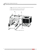
DRIVELINE UPGRADE INSTALLATION Remove the Existing Connecting Arms and Couplers REMOVING THE CONNECTING ARMS AND COUPLERS 1 Remove the four bolts and washers securing the existing connecting arms to the eddy current brake. Retain the bolts and washers. This hardware will be used to secure the new braces.
DRIVELINE UPGRADE INSTALLATION Remove the Existing Connecting Arms and Couplers 2 Remove the couplers from the dyno and the eddy current brake.
DRIVELINE UPGRADE INSTALLATION Install the Driveline and Brace Upgrade INSTALL THE DRIVELINE AND BRACE UPGRADE ................................... This section will walk you through installing the new driveline and brace upgrade. You will need to provide equipment capable of moving the eddy current brake. INSTALLING THE DRIVELINE AND BRACE UPGRADE 1 Slide the driveline on the eddy current brake shaft.
DRIVELINE UPGRADE INSTALLATION Install the Driveline and Brace Upgrade 3 Slide the eddy current brake up to the dyno. 4 5 6 Slide the driveline on the dyno shaft. Secure the braces to the dyno using the bolts and washers removed earlier. Tighten the driveline set screws. There is a set screw on each side of the driveline.
DRIVELINE UPGRADE INSTALLATION Install the Driveline and Brace Upgrade UPGRADING AND INSTALLING THE HOOD 1 2 3 Remove the eddy current brake hood from the dyno hood by removing the six 1/4-inch button-head screws and nuts. Secure the rear hood extension to the brake and dyno hoods using four 1/4-20 x 3/4-inch button-head screws and four 1/4-20 nuts. Secure the front hood extension to the brake and dyno hoods using six 1/4-20 x 3/4-inch button-head screws and six 1/4-20 nuts.
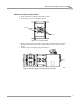
DRIVELINE UPGRADE INSTALLATION Install the Driveline and Brace Upgrade 4 Secure the top hood extension to the brake and dyno hoods using five 1/4-20 x 3/4-inch button-head screws and five 1/4-20 nuts. top hood extension Figure 11: Install the Top Hood Extension 5 6 Carefully place the fully assembled hood on the dyno leaving it propped up. Secure the key switch, if present. Lower and secure the hood using the four bolts removed earlier.
DRIVELINE UPGRADE INSTALLATION Install the Driveline and Brace Upgrade 7 Secure the hood keepers to the brake using the two bolts you removed earlier. 8 Secure the brake cover using the four bolts you removed earlier. Never operate the dyno with this cover removed.