©1993-2005 Dynojet Research, Inc. All Rights Reserved. Installation Guide For Model 248 Pit Automotive Dynamometers. This manual is copyrighted by Dynojet Research, Inc., hereafter referred to as Dynojet, and all rights are reserved. This manual, as well as the software described in it, is furnished under license and may only be used or copied in accordance with the terms of such license.
Contents Chapter 1 .......................................................1-1 Initial Setup and Requirements Introduction................................................................................. 1-1 Dyno Placement.......................................................................... 1-2 DynoWare EX+ Placement ......................................................... 1-4 Computer Placement.................................................................. 1-5 Requirements to Unload Truck..........
Contents Chapter 4 .......................................................4-1 Basic Dyno Operation Loading the Vehicle .................................................................... 4-2 Connecting the RPM Pickup...................................................... 4-5 RPM Pickup Descriptions ...........................................................................4-6 Connecting the Secondary Inductive Pickup ..............................................4-7 Connecting the Primary Inductive Pickup .
Chapter 1 Initial Setup and Requirements Thank you for purchasing the Dynojet Automotive Dynamometer. This document will give you the information you need to install the Dynojet Dynamometer (pit model). If you have any questions please call Dynojet at (800) 992-4993. Introduction Before installing your Dynojet Dynamometer, there are a few factors to consider.
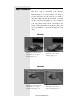
Dyno Placement The first step to installing your Dynojet Dynamometer is to decide where you want to position the Dyno in your shop. Do you want to drive the vehicle into the shop forward, or back it in? Do you have equipment or tools located in your shop that would be more convenient to use based on the placement of the Dyno? There are two basic methods to position the Dyno in your shop. Method 1 This image represents a front wheel drive car on a dyno near the garage door.
Note: The Dynamometer drums can rotate in either direction Choose the Dyno placement that best matches your shop and types of vehicles you work on. This image represents a dyno near the garage door. This image represents a dyno away from the garage door. Note: Refer to the technical drawings in Appendix A.
DynoWare EX+ Placement The DynoWare EX+ system is comprised of four modules: the CPU module, the Dynamometer Input/Output module, the RPM module and the Atmospheric module. The Dynamometer Input/Output module connects to the dynamometer. (A 20 foot (6.1 meter) long cable is provided.) The CPU module connects to a personal computer. (A 12 foot (3.7 meter) long cable is provided.) RPM Pickups and a Hand Held Pendant also connect to the modules.
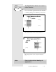
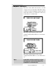
Computer Placement The driver of the vehicle must be able to view the computer monitor and the DynoWare EX+ during a run. If you will be running both front and rear wheel drive vehicles you will need to find a way for the driver to see them both. This image represents the location of the computer and DynoWare EX+ for a front wheel drive car. This image represents the location of the computer DynoWare EX+ for a rear wheel drive car.
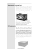
Requirements to Unload Truck When your dyno arrives, you must provide equipment to unload the dynamometer from the truck, with skids or forks a minimum of 6 inchs wide by 6 feet long. It must be capable of lifting and moving at least 8000 pounds (3642 KG). The dyno has 2 C-Channels that run lengthwise along the bottom of the dyno. Unload the dynamometer using these channels. Pit Requirements You must provide a dyno pit.
Requirements to Install the Dynamometer When you install the dynamometer, you need equipment capable of lifting and moving at least 8000 pounds (3642 KG).
Other Requirements Shop Air The dyno air brake requires a 3/8-inch air hose with a minimum pressure of 60 psi. You must provide 3/8-inch air line that will reach from the dynamometer to the Air Pressure Regulator and another air hose to connect the regulator to your shop air supply. Computer Requirements You will need to provide a computer system to run the WinPEP software. WinPEP 7 includes complete documentation in online Help. From the WinPEP 7 menu bar, choose Help WinPEP 7 Help or visit www.winpep.
Optional Accessories Covers Dynojet can provide optional covers for your Dynamometer. You may purchase these covers at an additional cost or build them from the diagrams in Appendix B. Extended Hand Held Pendant Cable 40 foot (12.
Uncrating the Dyno Step 1 Use a crowbar or the like to remove the plywood shipping shell from the dynamometer. • Remove the top of the crate. (If you ordered the dyno with the optional pit covers, they will be in the top portion of the crate.) • Remove the sides of the crate. • Remove the bottom skids and discard. Step 2 Carefully remove the cardboard boxes and brake weldments that are stored within the dynamometer’s frame.
Step 4 Verify that the cardboard boxes contain the following: Brake Hardware: • 2 brake weldments (The following are attached to the dyno frame) • six 5/8" bolts • six 5/8" lock washers • six 5/8" flat washers • six 5/8" nuts Mounting Hardware: 9- 1" UNC nuts 3- 1" Lock washers 6- 1" Flat washers Support Hardware: 2 Long lateral Supports 2 Short lateral Supports (in the non brake side of the dyno frame).
Ground Hooks: • 8 Ground Hooks Straps: • 2 axle straps • 4 ratchet straps • 2 ratchet straps with sleeves Chocks (4): 1 - 12 Document #98219100
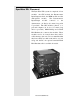
Chapter 2 Hardware Installation DynoWare EX+ The standard dynamometer electronics package is comprised of 4 interconnected modules: System Expansion Connector Atmospheric Sensing Module RPM Module Dynamometer Input/Output Module CPU Module Atmospheric Sensing Module: The atmospheric sensing module measures absolute pressure, air temperature and relative humidity.
RPM Module: The RPM module receives and processes signals from up to 2 inductive pickups for measurement of engine RPM. Each input has an automatic gain circuit to compensate for a wide variance of ignition systems. The green LED glows when the RPM module is receiving power. The amber LED flashes when an RPM signal is detected. A steady flash rate, proportional to engine RPM, indicates a good RPM signal. These connectors are the inputs for both primary and secondary inductive pickup clips.
Dynamometer Input/Output Module: The dynamometer I/O module sends and receives data from the dynamometer and the hand held pendant. The module also contains a buzzer and light which are activated when either the vehicle or dynamometer speed limit is approached. The green LED glows when the dynamometer input/output module is receiving power. The amber LED flashes proportionally to dynamometer drum RPM. This 25-pin receptacle connects to the shielded cable from the dynamometer.
CPU Module: The CPU module contains a 32-bit processor which acquires data from the expansion modules and communicates to the main computer running the WinPEP software. The processor queries the expansion modules to determine their identity and capabilities. The green LED glows when the CPU module is receiving power. The blue LED is lighted when data from the modules is being acquired and saved. One of these connectors is used to communicate to the main computer.
CPU Module: ..... Continued This connector provides a synchronization signal to a 3rd-party data acquisition system. This connector provides 12 Volt DC power to a 3rd-party data acquisition system. This connector accepts 12 Volt DC power from a power supply or battery. The adjacent LED glows bright green when power is properly connected. When this switch is on, power is supplied to all connected modules.
Primary Inductive Pickup Cable (not shown) Remote Switch Breakout Board to DynoWare Cable Cord from Power Supply Computer Serial Port Cable 2-6 Document #98219100
Chapter 3 Installing Dynamometer Now that you have the Dyno unpacked, you may begin the installation of the Dynamometer. Preparing Pit For Dyno Step 1 Your Dynojet Car Dynamometer is designed to sit on three anchor bolts cemented into the floor of the pit. Thread one jam nut (1" UNC nut) on each of the three anchor bolts in the floor. Step 2 Thread one leveling nut (1" UNC nut) on one of the three anchor bolts. Place a flat washer on top of this nut.
Step 4 Thread the remaining two leveling nuts (1" UNC nuts) and washers on the anchor bolts. Use a bubble level or transit to adjust the leveling nuts so they are level with the first leveling nut. Use the first leveling nut as a reference for the others. Warning!! Do not level all three nuts by measuring down from the top of the pit to the top of each leveling washer. The Dynamometer must sit level for correct operation.
Step 5 Holding the leveling nut so it CANNOT turn, tighten the jam nut to the leveling nut. Be careful not to move the leveling nut! Both the jam nut and the leveling nut should not move when the jam nut is tight. Repeat this for the other two leveling nuts. Double check the leveling nut height on all three anchor bolts with the level or transit.
Installing the Brakes Use the following steps to install the brakes on your Dynojet Dyno: Step 1 Locate the brake hardware. You should have six 5/8" bolts, six lock washers, six flat washers, six nuts (mounted on the dyno) and two brakes. Left Right Step 2 The brakes mount on the inside of the dyno frame with the air canister on the top. Identify the left and right brakes. As shown in the figure above, the brakes can only be mounted one way.
Step 3 Mount the brakes on the dyno frame. Use three bolts, three nuts, and three lock washers on each brake weldment. Remove the nuts and lock washers from the dyno frame leaving the bolts in place. Place the brake weldments over the bolts on the frame. Finish the installation of the brake weldments with the nuts and lock washers. Step 4 Install the air hose between the brakes, using the ports on the sides of the air canisters.
Wiring the Dyno The following hardware and wires are shipped in boxes with the dyno except the DynoWare EX+ (A) that is shipped separately with the WinPEP software. Refer to the following page for item descriptions.
Basic Kit: A: DynoWare EX+ Modules B: Air Brake Pressure Regulator C: Air Brake Control Valve (Replaced by N with Proportional Air brake systems) D: DynoWare EX+ Power Supply and Cord E: Wall Mount for DynoWare EX+ F: DynoWare Cable G: Dynamometer Control Pendant H: Serial Port Cable I: Primary Inductive Cable J1&2: Secondary Inductive Cables K: Mounting Hardware L: Pickup Card Optional Proportional Air Brake Systems: (M) Booster Valve Assembly (Replaces C) (N) Electronic Pressure Regulator (EPR) (O) DIN Ra
Step 1 Install the pickup card. Remove the pickup card and the 2 screws from the bubble bag. Attach to the pickup bracket on the dyno so the optical pickup is facing the axle and the 3 pronged plug is facing away. Turn the drum carefully and check to see that both pickup tabs on the dyno axle go through the center of the optical pickup on the pickup card. Step 2 Prepare the Breakout Board - Remove the Bubble Bag from the Breakout Board and bracket.
- The Data Acquisition Cable is coiled around the Breakout Board. Uncoil the cable and Plug the cable into the Pickup Card on the dyno. Standard Air Step 3 (Skip to Step 4) Proportional Air Step 3 Install the electronic regulator. Locate the DIN rail on the right side 4X4 post. The electronic pressure regulator snaps onto the DIN rail. Hook one side on the DIN rail then rotate electronic pressure regulator toward the DIN rail until it snaps into place.
Standard Air Step 4 Screw the Air Brake Control Switch into the top of the right hand air canister as in the picture below. Proportional Air Step 4 Install the Booster Valve Assembly. Screw the booster valve assembly into the right side brake canister. Tighten it so the air gauge is facing out as shown below. There are two air lines coming from the electronic pressure regulator labeled "IN" and "OUT".
The line labeled "OUT" is connected to the 3way valve. Push the hose in then hand tighten the fitting. Pull on the hose to ensure it is seated properly. If it moves, tighten the fitting more. The line labeled "IN" is connected to the brass cross. Push the hose in then hand tighten the fitting. Pull on the hose to ensure it is seated properly. If it moves, tighten the fitting more.
Standard Air Step 5 (Skip to Step 6) Proportional Air Step 5 Install the Temperature Sensor on the left 4X4 post. Locate the temperature sensor bracket on the left side 4X4 post. Install the temperature sensor so it is approximately 3" from the surface of the drum.
Standard Air Step 6 Connect the remaining wires to the Breakout Board. Fasten the two black wires into the connecting block in the connectors marked with the word BRAKE. (The 2 wires can go in either order.) Connect the yellow and black wires from the Brake Control to the two connectors marked with the letters -SIG-. (The 2 wires can go in either order.
Proportional Air Step 6 Complete the breakout board wiring as in the following descriptions: A B C D E (A) Data acquisition cable coming from the optical pickup on the dyno shown on the left. These four wires go to the section of the card Labeled “DRUM”: The red wire connects to R1. The white wire connects to W1. The black wire connects to B1. The silver wire connects to S1. (B) One yellow and one black wire go to the two connections Labeled “PRESS”.
(C) There are five wires in the cable that connects the EPR (shown left) to the breakout board in the spot labeled “Load Control”: The black wire connects to V-. The red wire connects to V+. The clear wire connects to 0+. The green wire connects to 0-. The silver or ground wire connects to SH. (D) The brake wires (shown left) come from the air switch on the Booster Valve Assembly. They connect to the two connectors on the breakout board labeled “BRAKE”. They can connect in either order.
Step 7 The Breakout Board jumper settings are preset, though it is important that they be checked to ensure they are set for your application. The jumpers circled in white above may need to be changed to look like one of the drawings below. (The wires in the picture above reflect a proportional air install. Ignore them if you are installing standard air.) Proportional Air Jumper Settings. Standard Air Jumper Settings.
Installing the Long Lateral Supports. Install both of the Long Lateral Supports on the brake side of the dyno. Thread the supports all the way into the dyno providing clearance during the pit installation. Lowering the Dyno Into the Pit Step 1 Remove the screws holding the dynamometer cover in place and remove the cover.
Step 2 Loop the straps around the shaft between the flange bearings and the drums. (If chains are used, then adequate protection must be placed between the shaft and the chain to insure that the shaft is not damaged by the chain.) Note: Several types of straps or chains can be used to lower the dyno into the pit. Dynojet recommends using continuous nylon loop straps. (Dyno weight = 6000 lbs. (2724 kg.).
Step 3 CAREFULLY lower the dyno into the pit. Align the three mounting tubes on the dyno with the anchor bolts. Lower the dyno until it rests on the leveling nuts and washers. (The mounting tubes are oversized so there will be play between the mounting tubes and the anchor bolts.) WARNING!! The equipment used to move the dyno must be capable of lifting over 8000 lbs. (3632 kg.).
Adjusting Lateral Supports Use the following steps to install the lateral supports: Step 1 Back out the Short Lateral Supports on the nonbrake side of the dyno until they fit snugly against the pit wall. Step 2 Back out the Long Lateral Supports on the brake side of the dyno until they are snug against the pit wall.
Step 3 Use the Lateral Supports to align the dyno in the pit. Once the dyno is aligned make sure all the Lateral Supports are tight against the pit walls, then tighten the jam nuts as displayed in the figures below.
Install a 1" flat washer, 1" lock washer and set nut (1" UNC nut) on each anchor bolt. Torque each set nut to at least 140 ft. lb. (190 Nm.). Connect the Dyno Step 1 Plug the 25 pin DynoWare Cable into the bottom of the Breakout Board and hand tighten the thumb screws. (This step finishes the electrical installation on the dyno.
Step 2 Connect your shop air to the dyno. Mount the Air Pressure Regulator on the wall in the shop with the bracket provided. Connect a supply air hose to the inlet of the regulator from your shop air supply. Note: Make sure the arrow on the regulator is the same as the direction of the air flow! Connect a 3/8" air hose to the outlet side of the regulator.
Install the Dyno Cover(s) Use the following steps to install the dyno cover(s): Step 1 Check the anchor bolts and lateral supports to make sure they are tight. Install the dyno cover. Step 2 Check the brakes. The DynoWare Stack must be on to release the brakes. Slowly rotate the drums (this can be done manually) then press the brake button (the red button on the Remote Pendant). The button should light up and engage the brakes stopping the drums.
Step 3 Install the optional auxiliary pit cover plates over your dyno. A sample layout drawing for the auxiliary covers is provided in Appendix B. If you have any installation questions, call Dynojet at (800) 992-4993.
Installing Ground Hooks Ground hooks are points at which you can connect the straps that hold down the car that is being tested. This keeps the vehicle from sliding side to side or off the drum of the dyno during a run. Forward and Back Shifting Side To Side Ground Hook Installation Hardware: Ground Hook: 8 or 10 Rings 8 or 10 Ring Plates Anchors: 16 or 20 Drop-In Anchors Bolts: 16 or 20 1" x 3/8" UNC Grade 5+ Setting Tool: Used for expanding the anchors.
Drop-In Anchor A drop-in anchor is a heavy duty internally threaded anchor used to bolt the ground hooks onto a concrete floor. Ground Hook Placements The placement of the ground hooks can be found in Appendix A.
Installing the Anchors Step 1 Using an Impact Drill, drill the two holes in the cement at each location on the drawing in Appendix A. (Use a ring plate as a template for the precise hole placement.) You will need a 1/2" drill bit to drill a hole to a minimum depth of 1 5/8". Clean the cuttings and debris from the hole. Clean out Debris Note: (1) The use of a carbide drill bit is recommended for the installation of this anchor. (2) Do not use core drills to drill hole for this anchor.
Step 3 Expand the anchor with the setting tool. The anchor is properly expanded when the shoulder of the setting tool is flush with the anchor. Step 4 Bolt the ground hooks onto the anchors to complete the ground hook installation.
Notes: 3 - 30 Document #98219100
Chapter 4 Basic Dyno Operation The Dynojet Dynamometer gives state of the art technology, durability, and accuracy that you need. Dynojet’s advanced engineering delivers the precise horsepower measurements a technician needs to make quick and accurate evaluations of engine performance and drive train problems. This chapter includes instructions for basic dyno operation. For more detailed instructions, refer to the WinPEP 7 User Guide. This manual can also be found on your WinPEP CD or at www.dynojet.com.
Loading the Vehicle Use the following steps to load a vehicle on the dyno. 1. Verify your computer is running. Set the dyno brake on by pressing the red button on the hand held pendant. 2. For four or all-wheel drive vehicles, measure the wheel base on the vehicle and adjust the 224-4WD dyno to that dimension before driving the vehicle on the dyno. CAUTION: Do not make any adjustments with the vehicle on the dyno. 3. Drive the vehicle onto the dyno and align the vehicle straight with the dyno. 4.
5. When the vehicle is positioned properly on the dyno, shut the engine off. • If the vehicle has an automatic transmission, place it in park. • If the vehicle has a manual transmission, place it in gear. 6. Set the vehicle’s emergency brake. 7. Secure the non-drive wheels using the provided tire chocks. Do not use tire chocks for four wheel drive vehicles. 8. Attach the tie-down straps. Rear Wheel Drive • Attach two tie-down straps from secure anchor points to the rear of the vehicle.
9. Tighten the tie-down straps evenly making sure that the drive wheels remain centered on the drum. CAUTION: The tie-down straps should always be connected to the vehicle’s solid axle or the suspension control arms. Factory tie-down hooks connected to the vehicle’s frame may be used on the end opposite the drive wheels (for example: the front end of a rear driven vehicle). 10. Release the brake on the vehicle and the dyno. 11. Start the vehicle and put the transmission into first gear or drive. 12.
Connecting The RPM Pickup Your Dynojet dynamometer includes a primary wire inductive pickup and two secondary wire inductive pickups. These small “clothespin like” inductive pickups are used to sense RPM. An RPM pickup is required if you want to view torque graphs. Generally you will use one secondary wire inductive pickup on a spark plug wire. Vehicles with wasted spark ignition systems may require two secondary inductive pickups.
RPM Pickup Descriptions RPM pickup Secondaries (Non- wasted spark system) Secondaries (Wasted spark ignition system) Primary pickup Optional Optical RPM Sensor 4-6 description Use one secondary pickup. Unplug the other pickup from the RPM module and set the degrees between plug fires to 720° in WinPEP 7. Use two secondary pickups. Attach one pickup on each spark plug wire on the same coil and set the degrees between plug fires to 360° in WinPEP 7.
Connecting the Secondary Inductive Pickup The secondary inductive pickup cannot be in contact with, or it’s connecting wire be crossing, other engine electrical wires or stray RF interference may result. 1. Clip the secondary inductive pickup around one spark plug wire. 2. Route the inductive pickup cable clear of devices that produce electronic noise (spark plug wires, coil wire, coil etc.) to the dyno electronics RPM module. Note: Inductive pickup placement is important.
Connecting The Primary Inductive Pickup The primary inductive pickup cannot be in contact with, or it’s connecting wire be crossing, other engine electrical wires or stray RF interference may result. 1. Clip the primary inductive pickup around the wire to the primary side of the coil. 2. Route the primary wire cable clear of devices that produce electronic noise to the dyno electronics RPM module. Note: You must ground the vehicle to the dyno for the electronics to function properly.
Pre-run Inspection Perform a vehicle inspection before making a run. • Check the radiator coolant (if applicable) and oil levels. • Check the fuel source. • Rotate the drum and check for rocks caught in the tire tread that could fly out. • Check the tire pressure and tire speed rating. Improperly inflated tires or exceeding the maximum speed rating can result in premature wear or severe tire damage. Make sure the tire has no major deficiencies (cracks in sidewalls, tread life, etc.).
Engine Warm Up Warm the vehicle’s engine and drivetrain before beginning testing. Consistent engine temperatures will assure your runs are repeatable. After Engine Warm Up Always leave the vehicle in neutral (automatic transmission) or in first gear (manual transmission), with the engine off, and make sure the park brake and the dyno brake are on when you get off the vehicle on the dyno. • Fix any fuel, oil, or coolant leaks that may have shown up after engine warm up and check the carburetor for leaks.
Making a Test Run Dyno runs provide safe, reliable road testing right in the shop. The dyno allows you to measure, record, and diagnose performance problems quickly. The dyno combined with WinPEP 7 produces consistent, easily interpretable power graphs. Use the following instructions to ensure repeatable and accurate measurements. 1. Verify the vehicle is secured properly. 2. Place the vehicle in a low gear and release the dyno brake using the hand held pendant. 3. Slowly accelerate the vehicle to 20 m.p.h.
Appendix A Ground Hook Layout Ground hook diagram with the pit near the front of the shop. Align Pit and Dynamometer to the center of door opening for ease of use.
Ground hook diagram with the pit near the back of the shop. Align Pit and Dynamometer to the center of door opening for ease of use.
Appendix B Auxiliary Cover Plate Diagrams Document #98219100 Appendix B - 1
Appendix B - 2 Document #98219100
Document #98219100 Appendix B - 3
Appendix B - 4 Document #98219100
Document #98219100 Appendix B - 5
Appendix B - 6 Document #98219100
Document #98219100 Appendix B - 7
Notes: Appendix B - 8 Document #98219100