
Installation Guide User Manual


INTERFACE ROLLER ASSEMBLY INSTALLATION
Interface Roller Assembly Installation
Version 4 Above Ground Model 224 Automotive Dynamometer Installation Guide
C-3
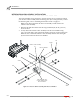
3 Align the rollers on the interface roller assembly with the interface tube on the
dyno.
Note: The distance between the dyno and the lift may need to be adjusted.
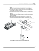
4 Using the 1/2-inch and the 1/4-inch thick shims as necessary, adjust the interface
roller assembly to fit the lift cross member.
5 Lower the lift until the interface roller assembly just starts to enter the interface
tube.
6 Tighten the hardware securing the interface roller assembly to the lift cross
member.
Note: The interface roller assembly mounting bolts should touch the bottom of
the lift cross member.
7 Raise and lower the lift several times to make sure that the interface roller
assembly is working smoothly. Adjust the interface roller assembly if needed.
8 Verify the lift can be lowered down to floor level.
Figure C-2: Align the Interface Tube and the Interface Roller Assembly
SA018
interface tube
interface roller assembly
shim
mounting bolt
lift cross member